Photon has added Tutorial 22 and 23, click on the menu -> Tutorials -> Amiga Assembler and look in the bottom.
Or check out the whole playlist here

Photon has added Tutorial 22 and 23, click on the menu -> Tutorials -> Amiga Assembler and look in the bottom.
Or check out the whole playlist here
 Next issue of Run is added, Issue 18 August 1986
Photon added video #21 of his assembler tutorial series.
 Next issue of the Danish Run magazine is added, this is issue 17, 6/7 1986.
It’s been a while, but Photon has made 5 more tutorials, 16-20.
Check them on the youtube list
Someone in the Danish amiga community asked if the 68010 is faster than the 68000.
The short answer is No, and the long one Yes.
There is a slight improvement which you might be able to feel for CPU intensive work. But for gaming? naaa.. you might see a slight smoother scrolling for vector based games.
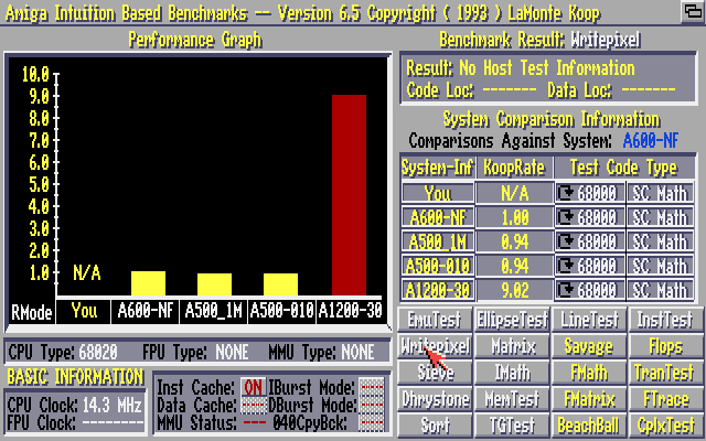
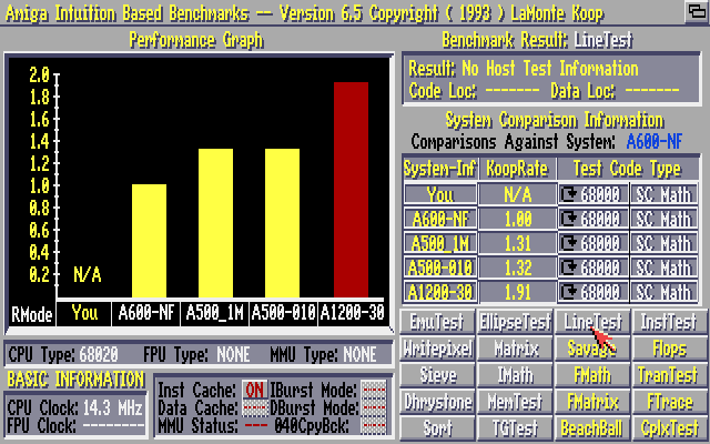
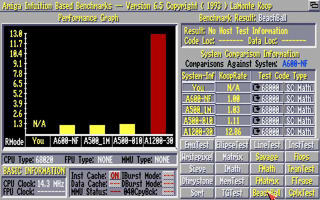
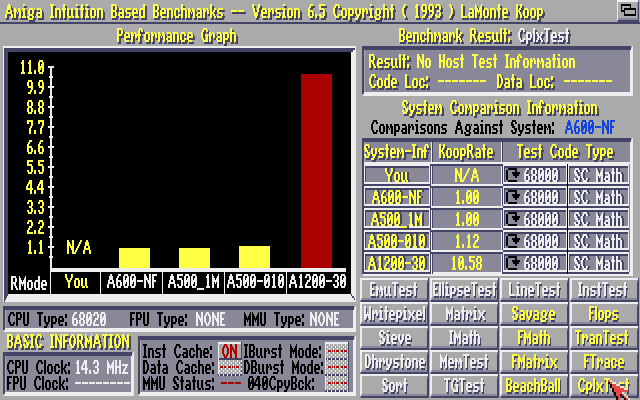
For the tests, I’ve created a bootable floppy. It has Sysinfo, WhichAmiga and AIBB on it. And I’ve chosen AIBB as benchmark program for this test.
I’ve used the same A500 for both tests, with a 512KB ram upgrade getting up to 1MB. The A500 ran Kickstart 1.3. Nothing other than switching out the 68000 with the 68010 has been done with the 2 A500 systems
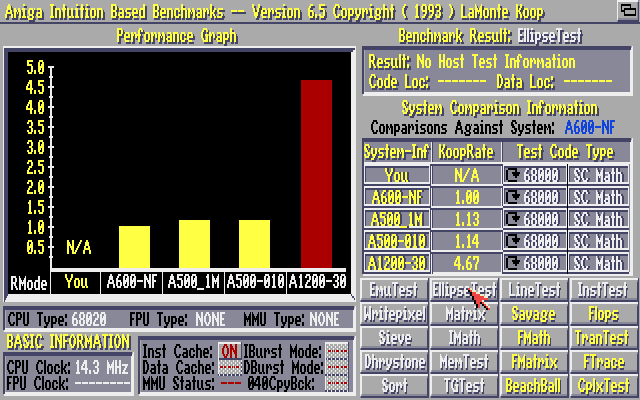
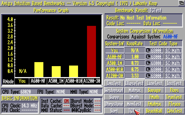
You’ll see 4 systems in the images
A600-NF – This system comes with AIBB, and I can guess it’s a stock A600 (68000)
A500_1M – A500 with 512kB ram upgrade (68000@7MHz)
A500-010 – A500 with 512kB ram upgrade (68010@7MHz)
A1200-030 – A1200 Blizzard1230 MK IV 030@50MHz, 64MB ram


It is rumoured that there are quite a few applications that require a 68020 actually runs fine on the 68010 due to instructions needed are in the 68010. I haven’t seen any of these applications, but if you find any please report them here so I can add them to a list. If you run into issues using 68010, the Decigel software might help you out.
Otherwise I’ll let the numbers speak for themselves and make it up to you to decide if you want to upgrade your system.
You can download the diskette with the modules created here.
If you only want to preview the results without testing on your own system, you can go to the menu “Special” and activate “Preview mode”.
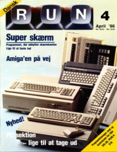 Run Issue 15 (Danish). Nr 4, April 1986 is now added to the site.
One of the problems with the Commodore and Philips monitors models C=1084, C=1084S, C=1081 etc, CM8833, CM8833-II, is the power switch is no longer able to be “stuck” in it’s ON mode. These are generally easy to replace if one can find a replacement unit.
I recently got some power switches off a guy from Amibay, these aren’t the exact same models as the ones used for the monitors, but they are still useable.
The switch is originally produced by Preh and is called ME5A, but there are quite a few models of these, and they aren’t written on the switch itself. So if you hunt down the switches, make sure you atleast get to see if the pins are meant for PCB soldering or just wires. The ones I received are solderable into the PCB, thus also useable for wires.
The original model number for the C1084S is: PREH ME5A 70060-062 (NS28)
The replacement used here is: PREH ME5A 70060-232 (NS11)
I found a dealer here: https://www.hwh-electronic.com/Power-Switch though it’s for business customers only.
Update 2016-02-22: Keir Fraser dropped this link in facebook: http://www.pollin.de/shop/dt/OTk4OTc1OTk-/HiFi_Car_HiFi_Video_TV/TV/Ersatzteile/TV_Netzschalter_PREH_TV3.html
If you know how to use a solder iron, and know your way around cables, this should be easy for you otherwise you should contact a professionel or atleast someone experienced to help you out.
This whole procedure can be done in 10-15 min.
WARNING: the CRT monitors have high-voltage inside and can give you shock if you’re not properly protected or careful. Touch only on plastic.
DISCLAIMER: if you by any means, hurt yourself or your equipment, I can’t be held responsible for any damages done.
UPDATE 2012-12-11 :A (badly made, which was made spontaneously with a smartphone) video showing the CM8833 monitor and how to unplug the 2 wires and access the power switch is shown in the bottom of this article.
Before starting, unplug the power chord, and any other cables attached to the monitor.
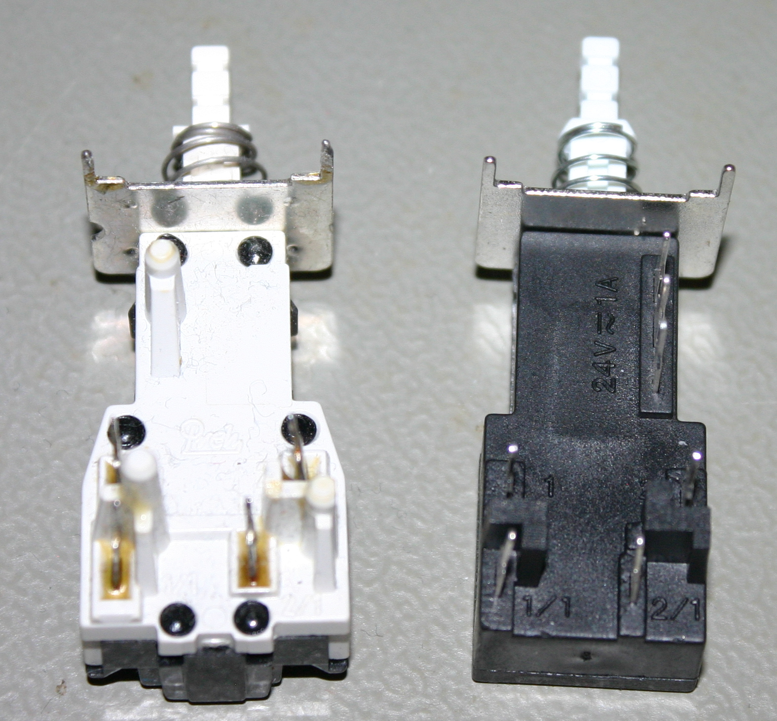
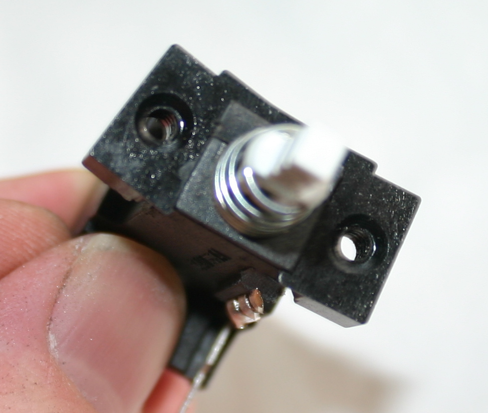
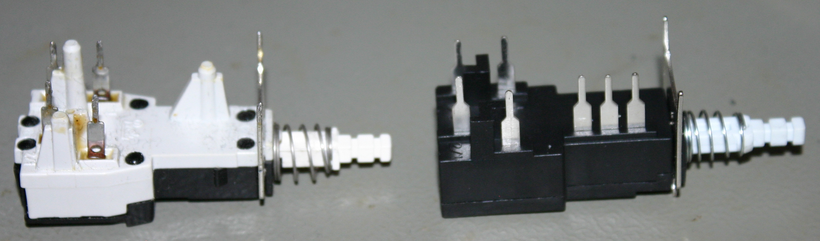 The switch to the left is the original one (from 1084S, I didn’t take a picture of the one from the 1084), and the one to the right is the new one.
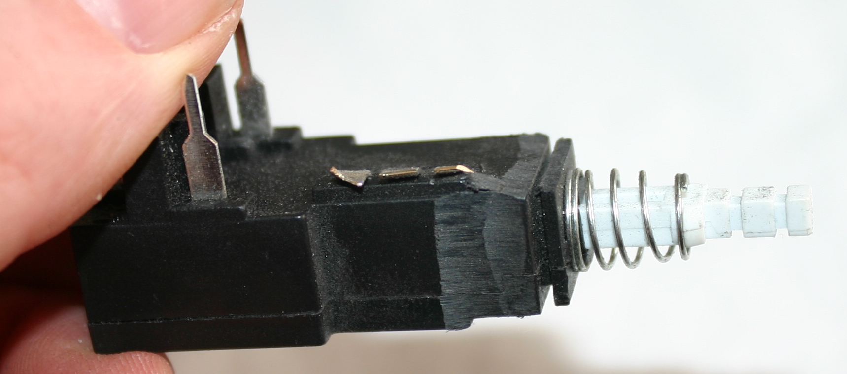 The ones I received here has a few extra pins which aren’t needed for our purpose, so we’ll just cut these pins off.
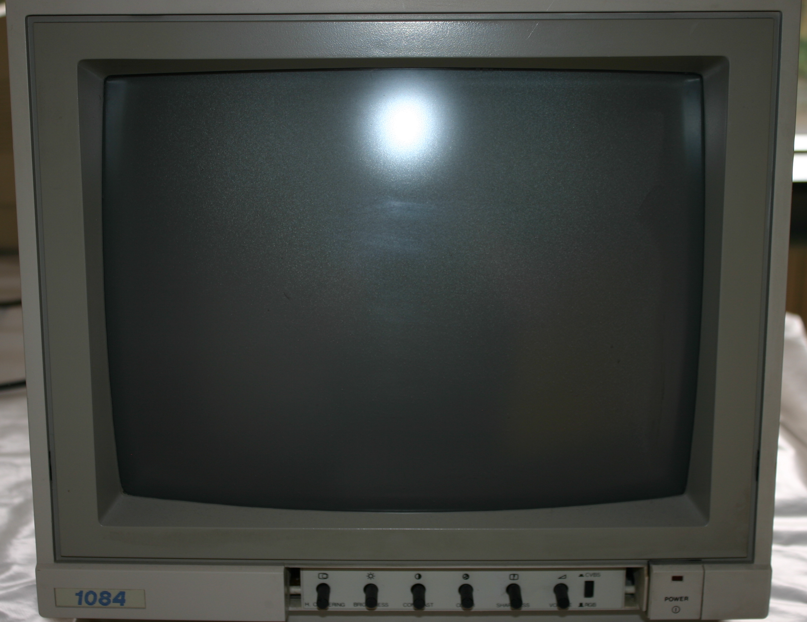 The 1084 Monitor with the power switch in the front.
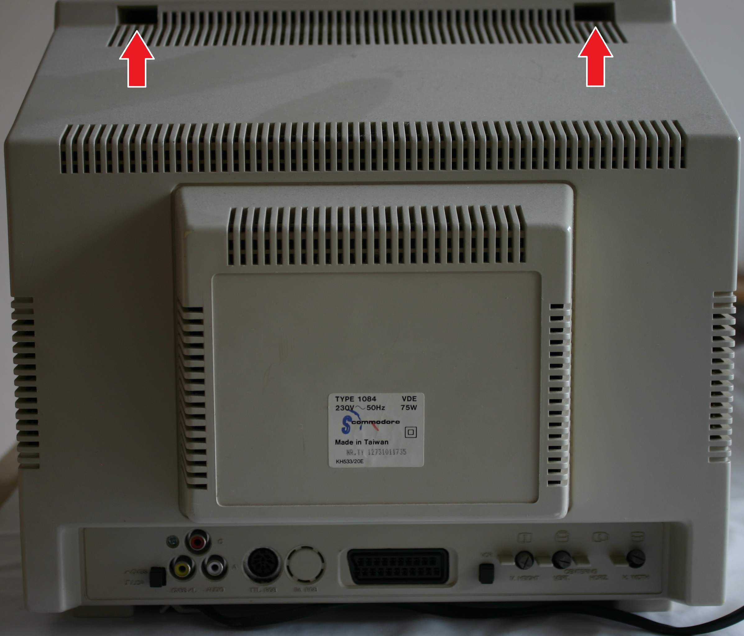 Remove the philips head screws in the holes where the arrows point.
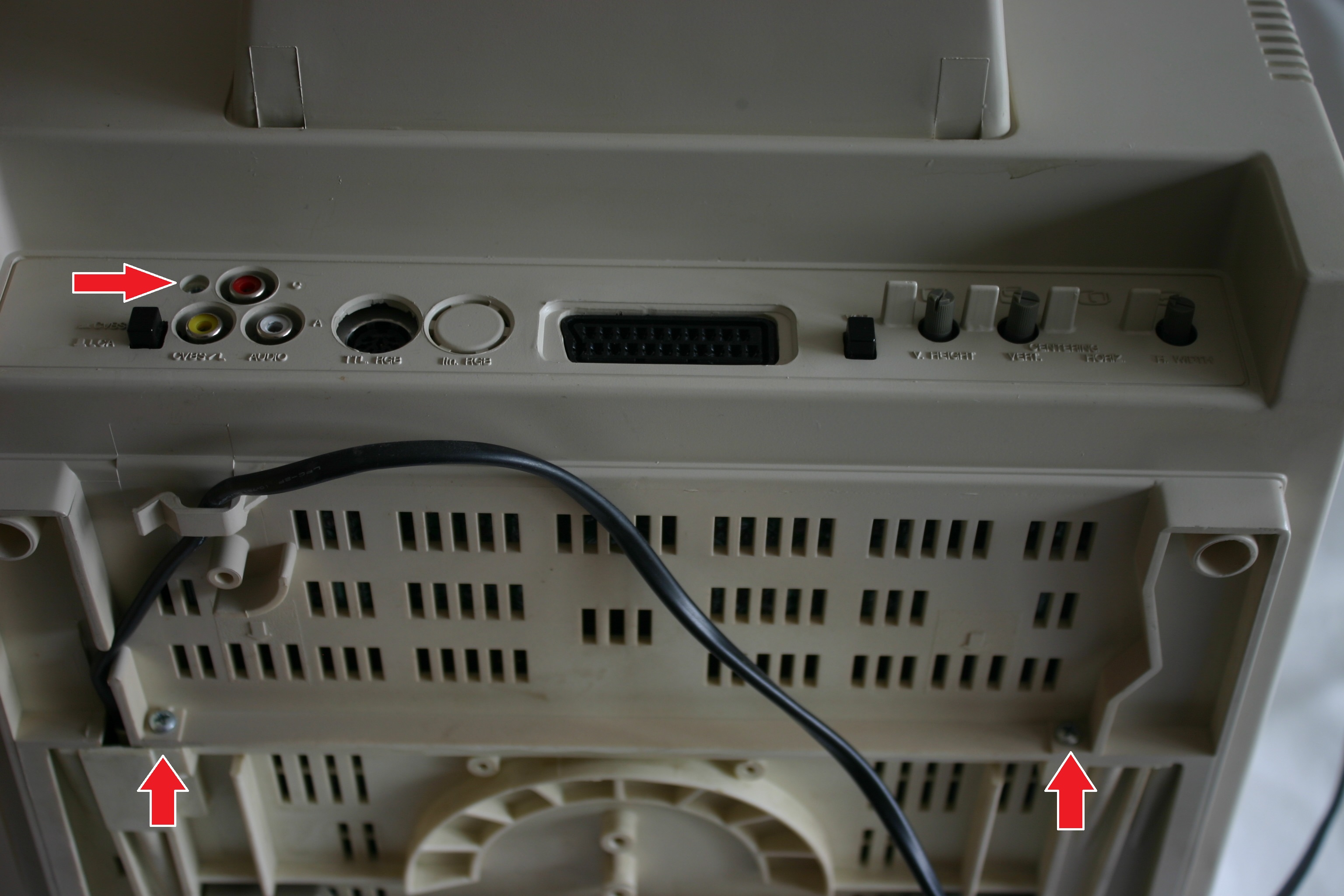 Remove the philips head screws in the holes where the arrows point, remove the 2 in the bottom first before unscrewing the one close to the audio/video output.
Make sure the power chord is removed from it’s holding clip.
Now you can gently slide off the back of the monitor. Be careful not to touch anything not plastic, as you can get hurt.
There might be a wire attached inside, to the back you’re pulling off, this wire can easily be removed. Just remember where it was located before assembling again.
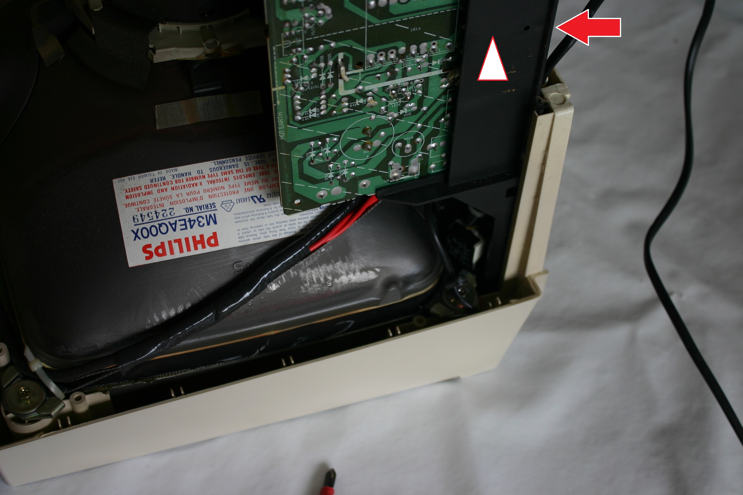
There is a small plastic tap that needs pushing around the area where the red arrow is pointing, when that is pushed the small PCB in the plastic can easily slide up.
There is a wire connected to this board, which should be removed before pulling up the PCB.
Now that you have access to the switch, remove the 2 screws, and unsolder the power wires (or cut them, just make sure you cut as little as possible as you need the full length of the wire)
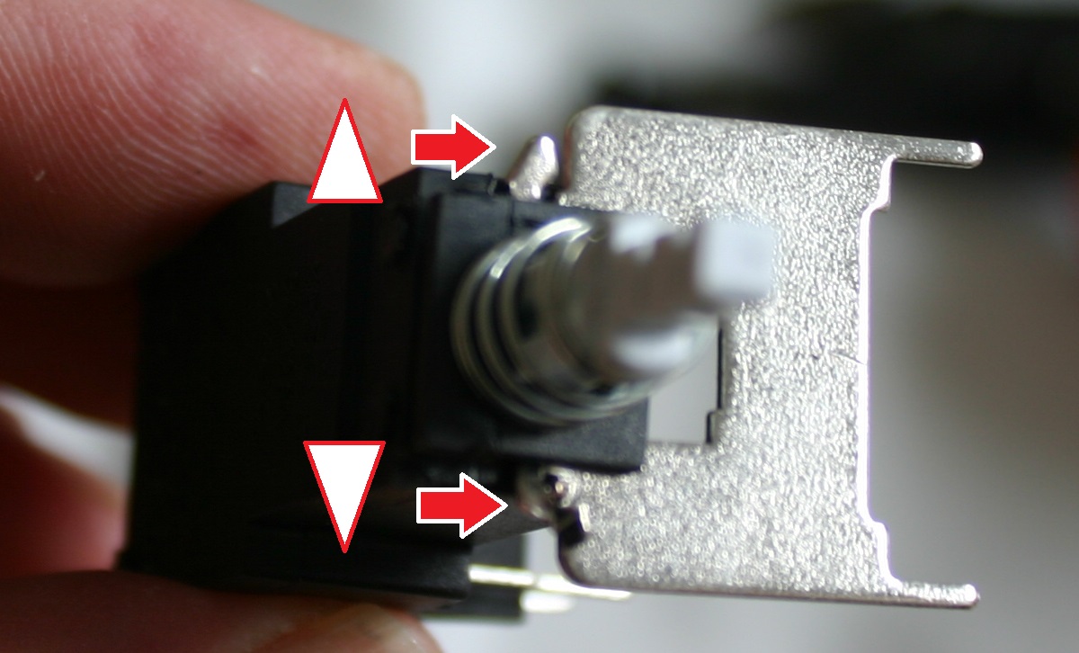
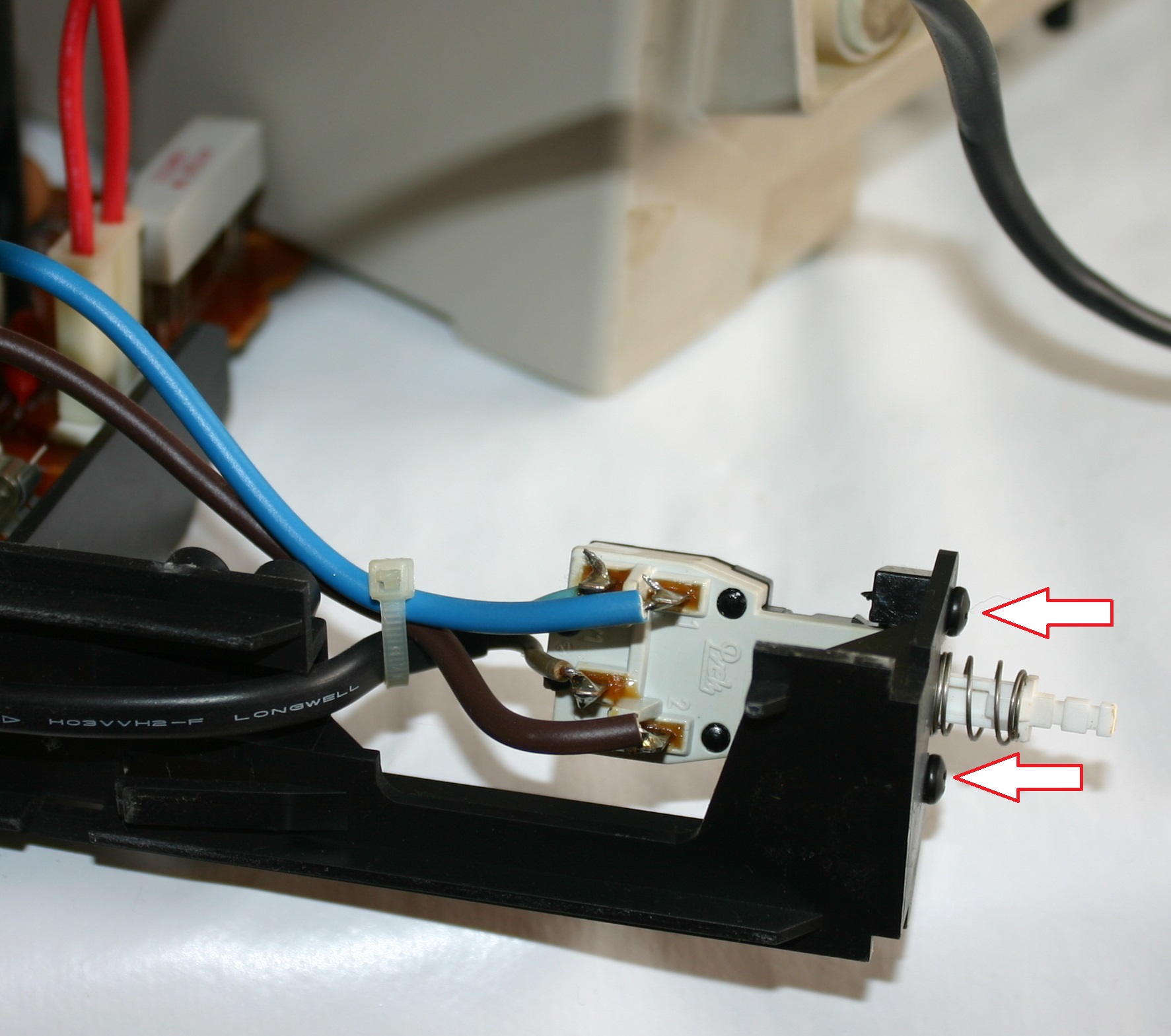
On the power switch I received it had a mounted plate, this can be removed by using pliers bending back the metal locks (white arrows), and gently pulling off the plate (red arrows).
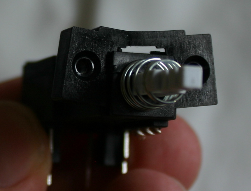
The plastic bracket on the old switch is needed, so gently pull this off.
It didn’t fit on the switch I had so I had to do a little sanding.
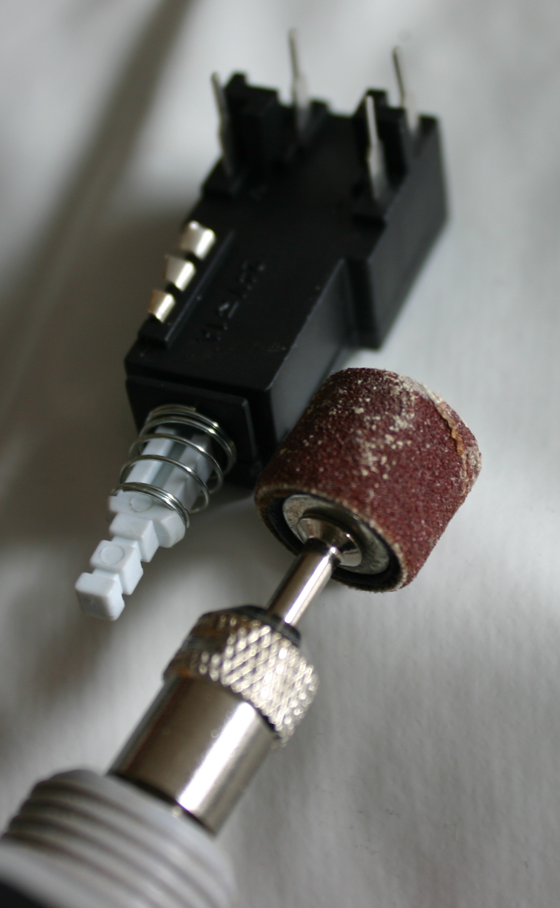
I used my dremmel to sand down the plastic in the sides and bottom.
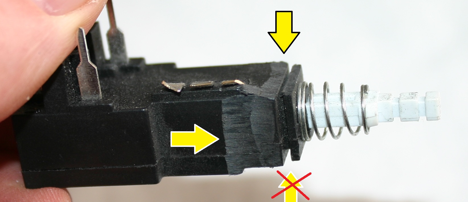
The result looks like this, I had to try mounting the plastic bracket several times before I was satisfied.
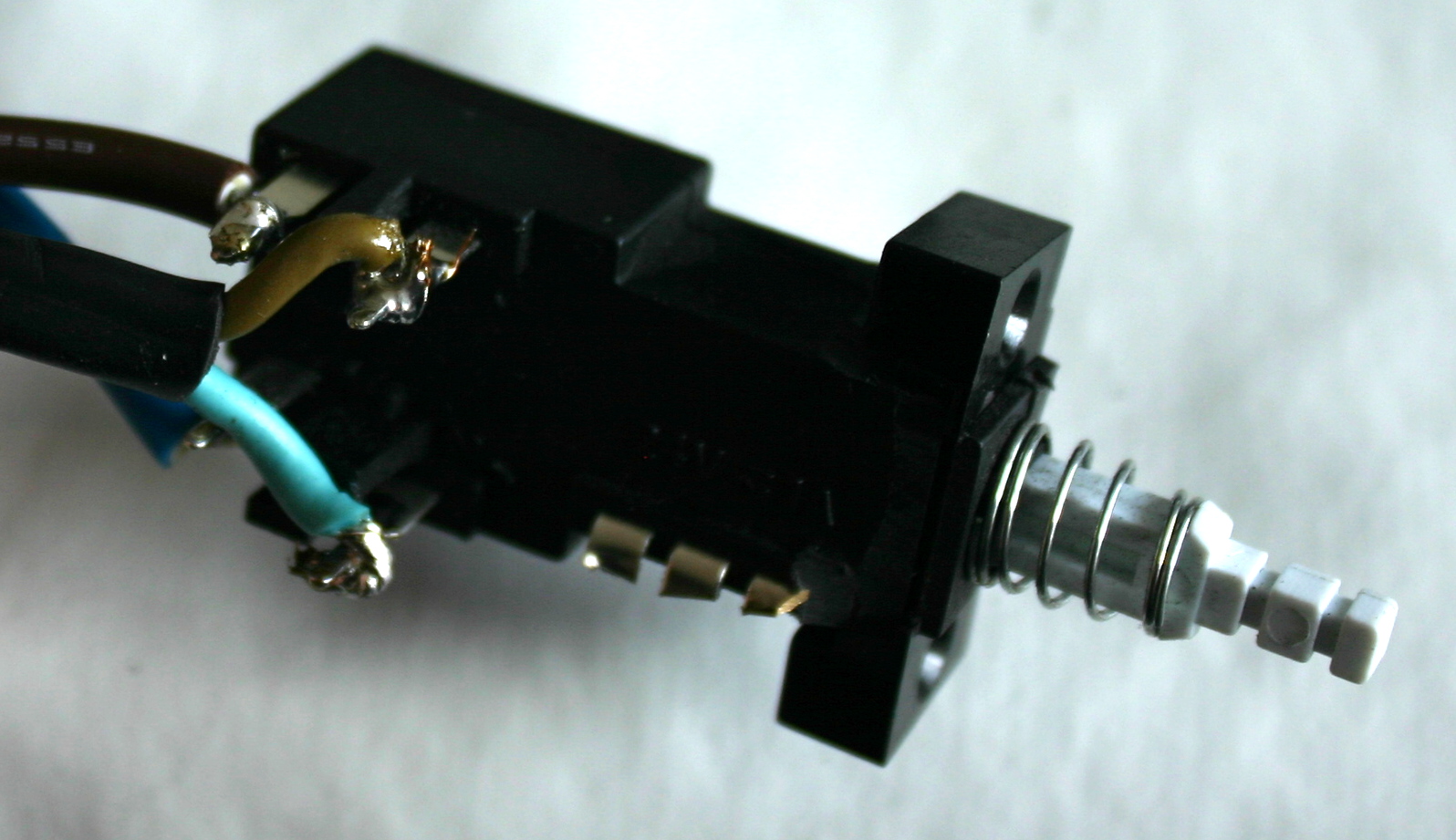
Time to solder the power wires onto the switch. Make sure that you have one set of cables to the back of the switch, and the other towards the front. Brown needs aligning to brown and blue needs aligning to blue. On the picture the cables going to the monitor are soldered to the leftmost pins, brown up/blue down, and the power chord is soldered to the right most part of the switch, brown up/blue down.
All you have to do now is mount everything back the way it was.
And you’re done.
A video showing the Philips CM8833 monitor (which is almost identical to the C= 1081) and how to access the power switch.
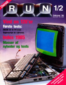 Next magazine of Run (Danish) is added to the site, this is Issue 13, February 1986