While the 1541 Ultimate 2 tape extender has a good length for the C64 and C128, it’s not long enough for the C128D, nor does it fit in the tape slot. Here’s a small hack that I’ve made to fix that.
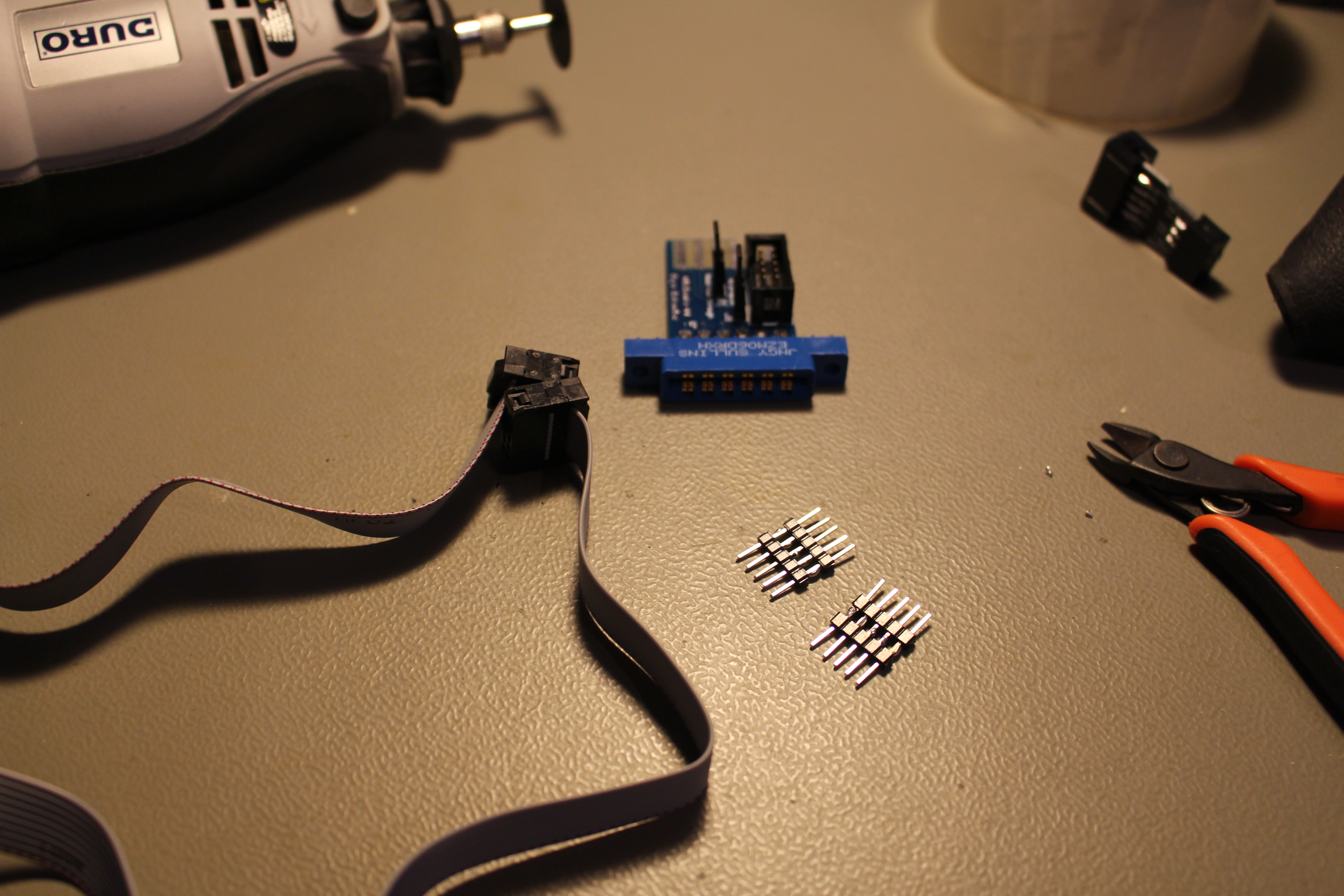
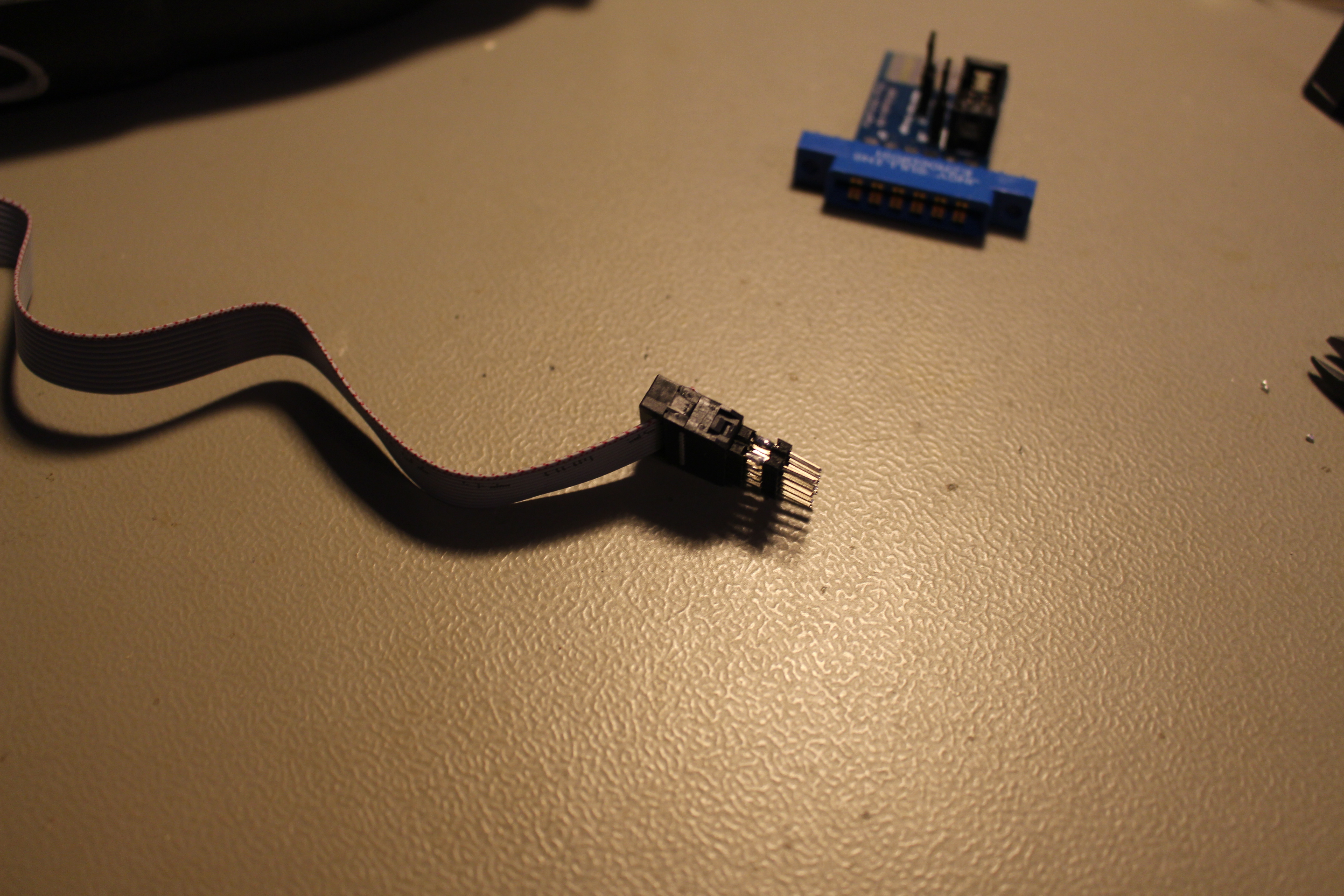
I only had SIL headers available when I made this, so I soldered 2 x 2×5 pins together creating a 10p male-male IDC header. I had to custom make the cable as it didn’t make a 1:1 connection from the original extender cable to the tape header.
If you’re creating one like this, make note that a standard 10p IDC cable doesn’t work here as the extender cable isn’t standard connected to the header. All odd numbers on the extender cable is connected to even numbers on the IDC header, though the direction is corret. See table below for reference.
Extender pin
IDC Cable pin
1
2
2
1
3
4
4
3
5
6
6
5
7
8
8
7
9
10
10
9
The tape header on the extender is too wide to be plugged into the C128D. I was lazy and only connected 6 wires here, but recommended is connecting all 10 to prevent noise/stray signals (Thanks e5frog).
This is something a Dremmel can take care of, just cut off the additional plastic used for screws.
Violá, ready to use the 1541 Ultimate 2 tape extender.
In the retro community there are a lot of different modern hardware these days, not always do they come in nice boxes.
The PCB’s can easily scratch the surface of the table, and aren’t protected against transportation etc.
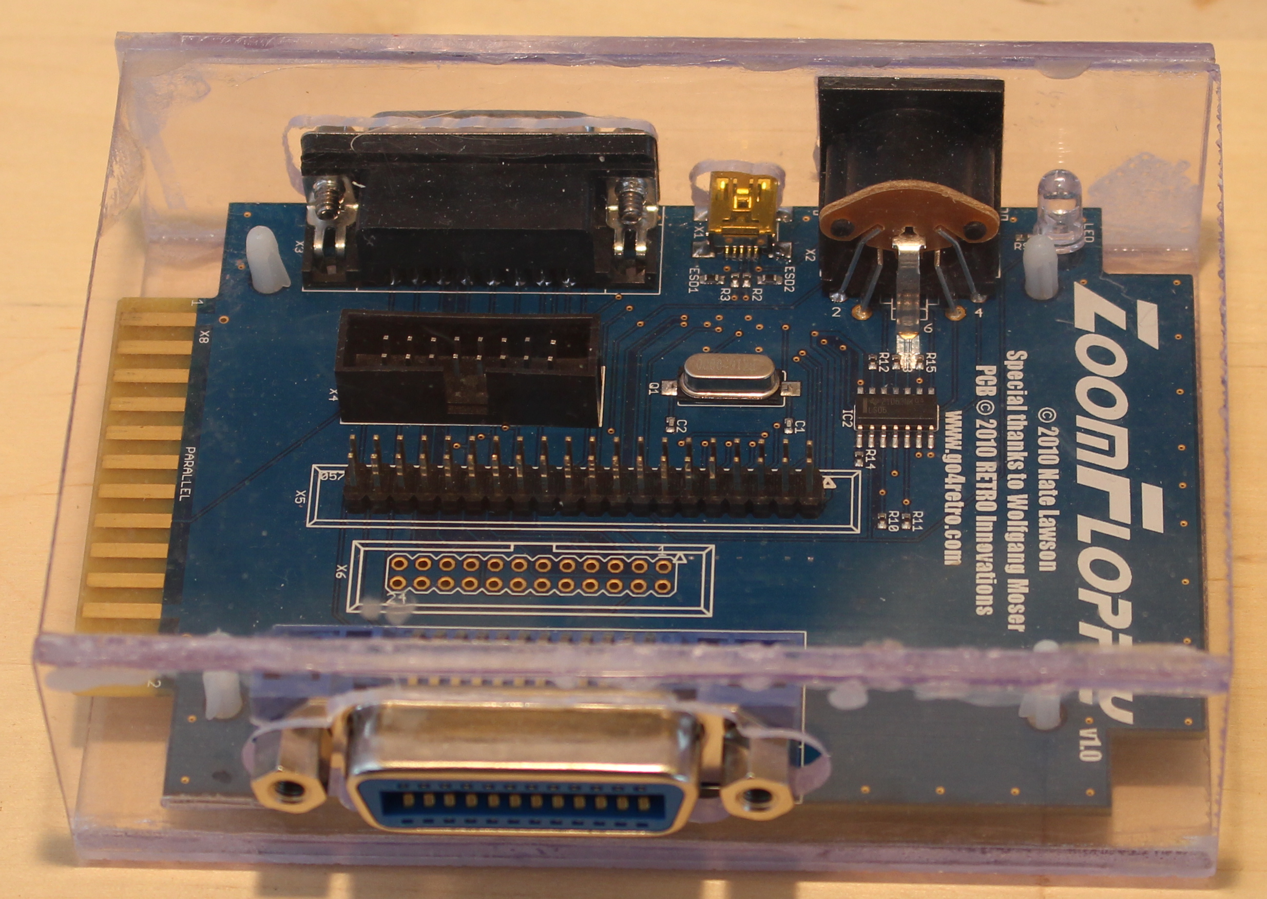
Last year I made a box for my ZoomFloppy and while it was my first box, and I wasn’t all that careful trying to get it to look nice, the box is still intact.
Last night I talked to a fellow DYI guy with plenty of ideas. He got hooked by the idea of using acrylic plastic to makea box for some electronic boards. He probably have better skills, tools and whatnot than I doing this kind of things.
I’ve used Acetone to “glue” the sides together. I can say, if acetone comes onto places where it shouldn’t, let it evaporize. If you try and wipe it off it’ll smear. The acetone seems to dissolve the acrylic glass.
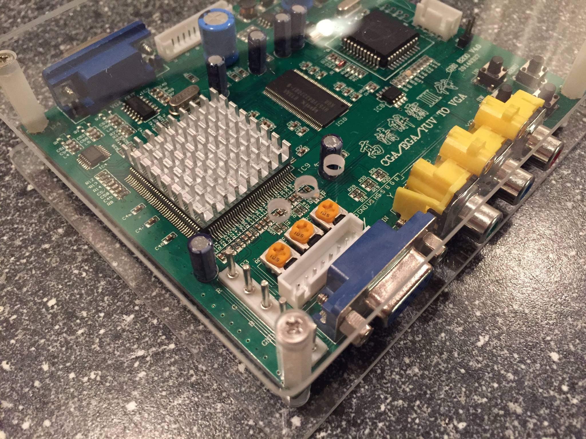
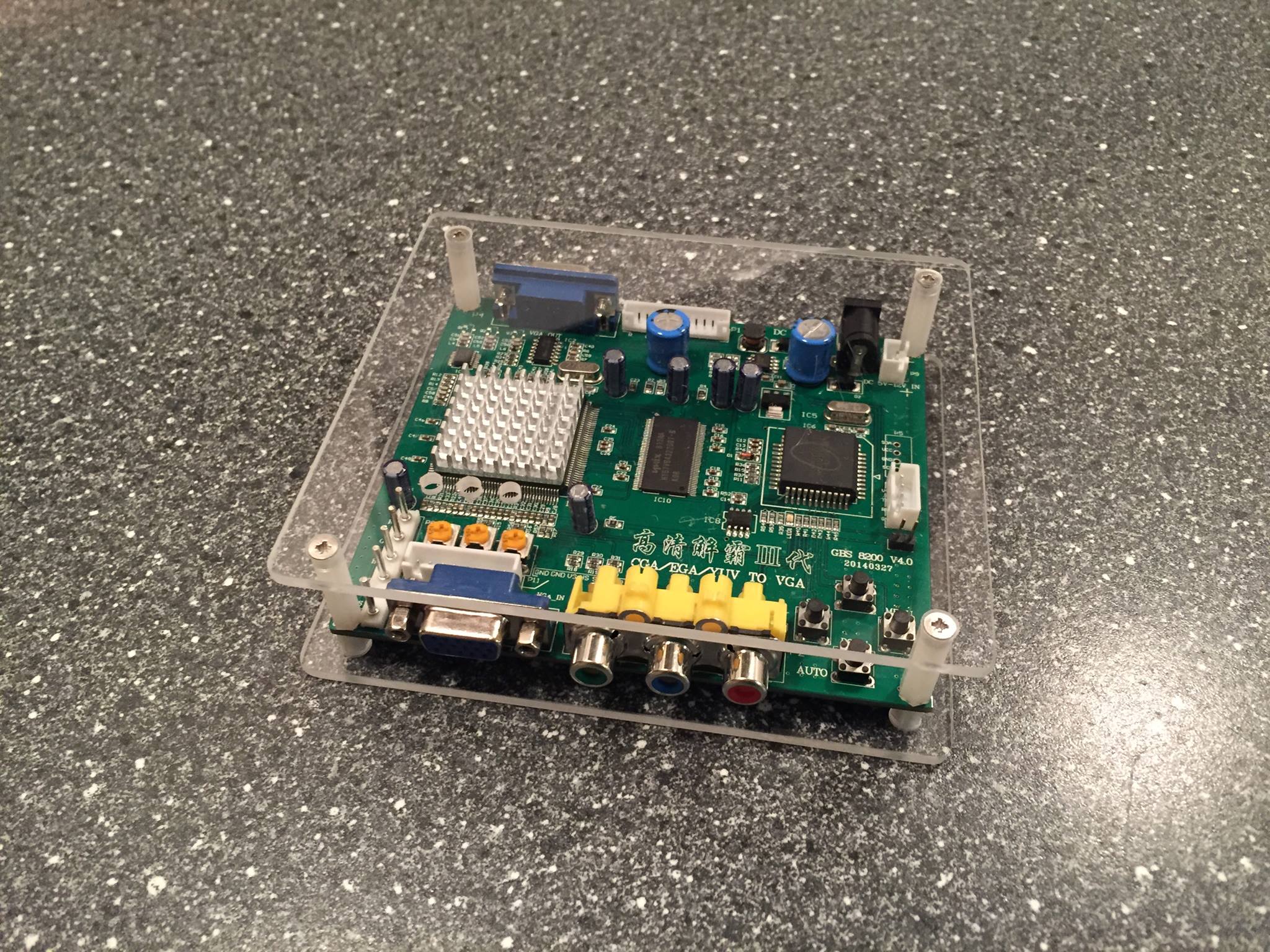
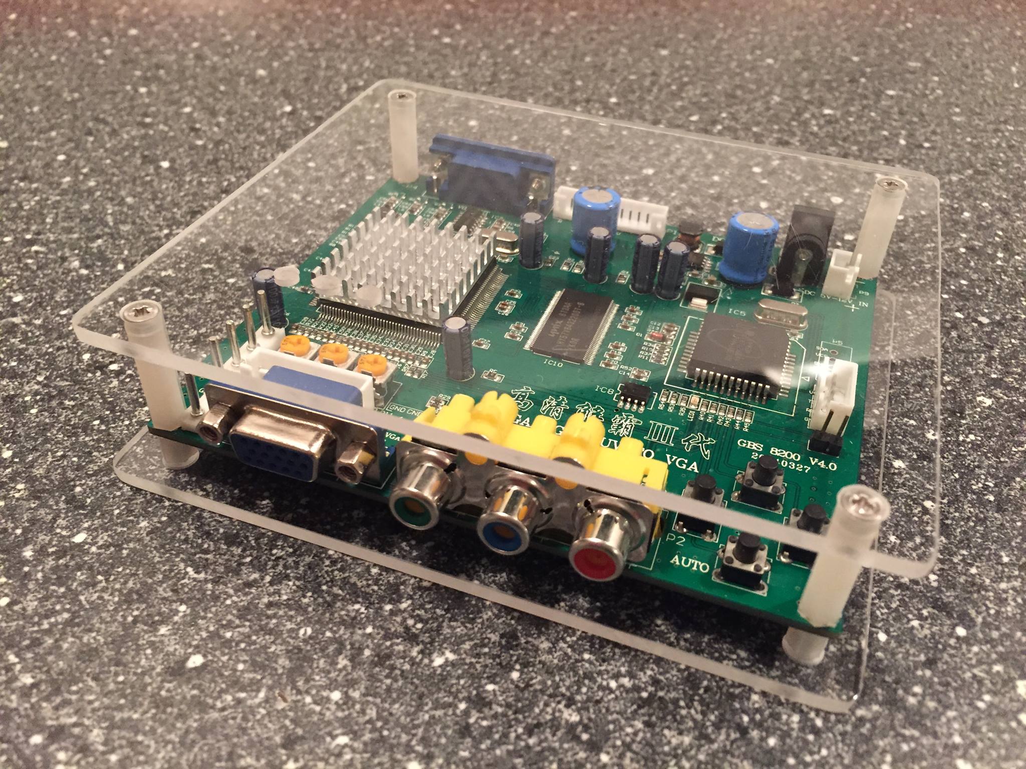
Here is an other example of creating a box, this doesn’t involve gluing, just acrillic spacers. This box was made by Henrik Christensen from Facebook, and used with permission here.
I must confess Henrik is more skilled than I 🙂 it looks great doesn’t it?
Since yesterday I’ve been making a backup of my NAS box that contains all the scans. I got a Synology 214SE in January with 2 2TB drives configured as RAID 1 / Mirror. These days the total amount of free space is around 200Gigs. I bought 2 3TB’s for this upgrade and while the backup takes time I can’t work with scans.
So while I’m taking a backup I might as well make a nice little post.
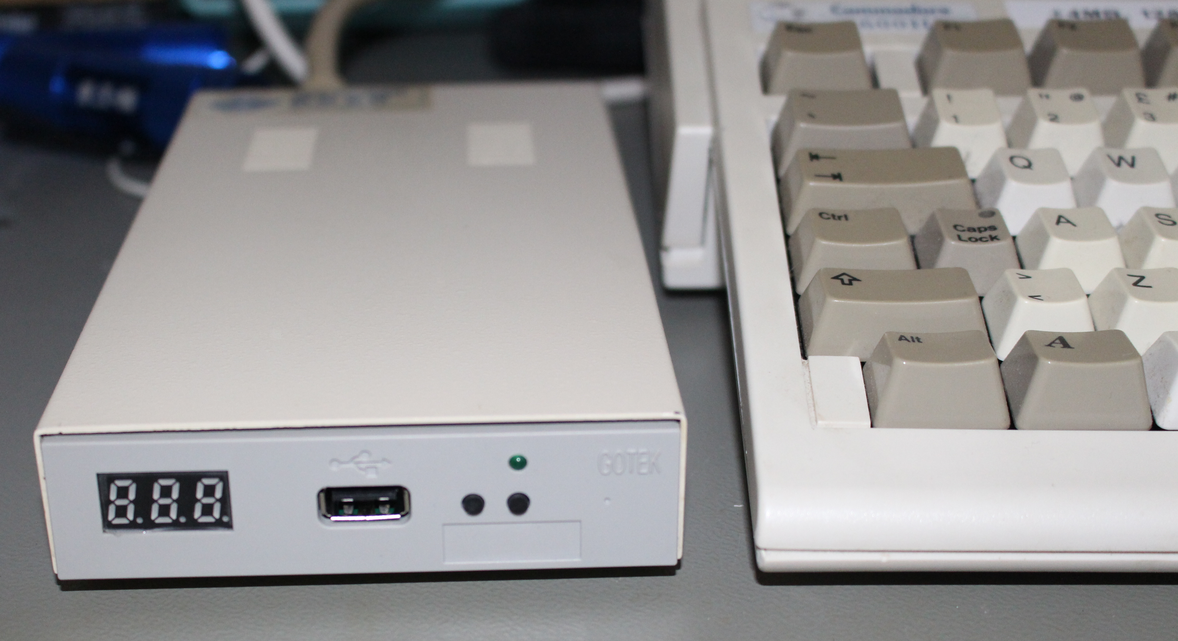
I’ve previously had some issues in adding a GOTEK drive into my external drive enclosures for the Amiga. So I’ve had this project shelved. Today I took one of the other enclosures and tried that. Yes this one works.
For you who don’t know what a GOTEK drive is, I’ll make a short explanation of it. It’s a floppy to usb emulator. You can use a USB drive and attach it to this device which is then plugged to the floppy controller of the computer, sewing machine, keyboard etc.
Hervé Messinger made a guide and a firmware so it can be used in the Amiga. See his project site: http://cortexamigafloppydrive.wordpress.com In the current firmware (1.05) there are some qirks that still needs fixing, i.e. cannot format a disk, nor use track copy applications like X-Copy.
The GOTEK drive can be aquired for around $19 on eBay (price update 2015-02-21).
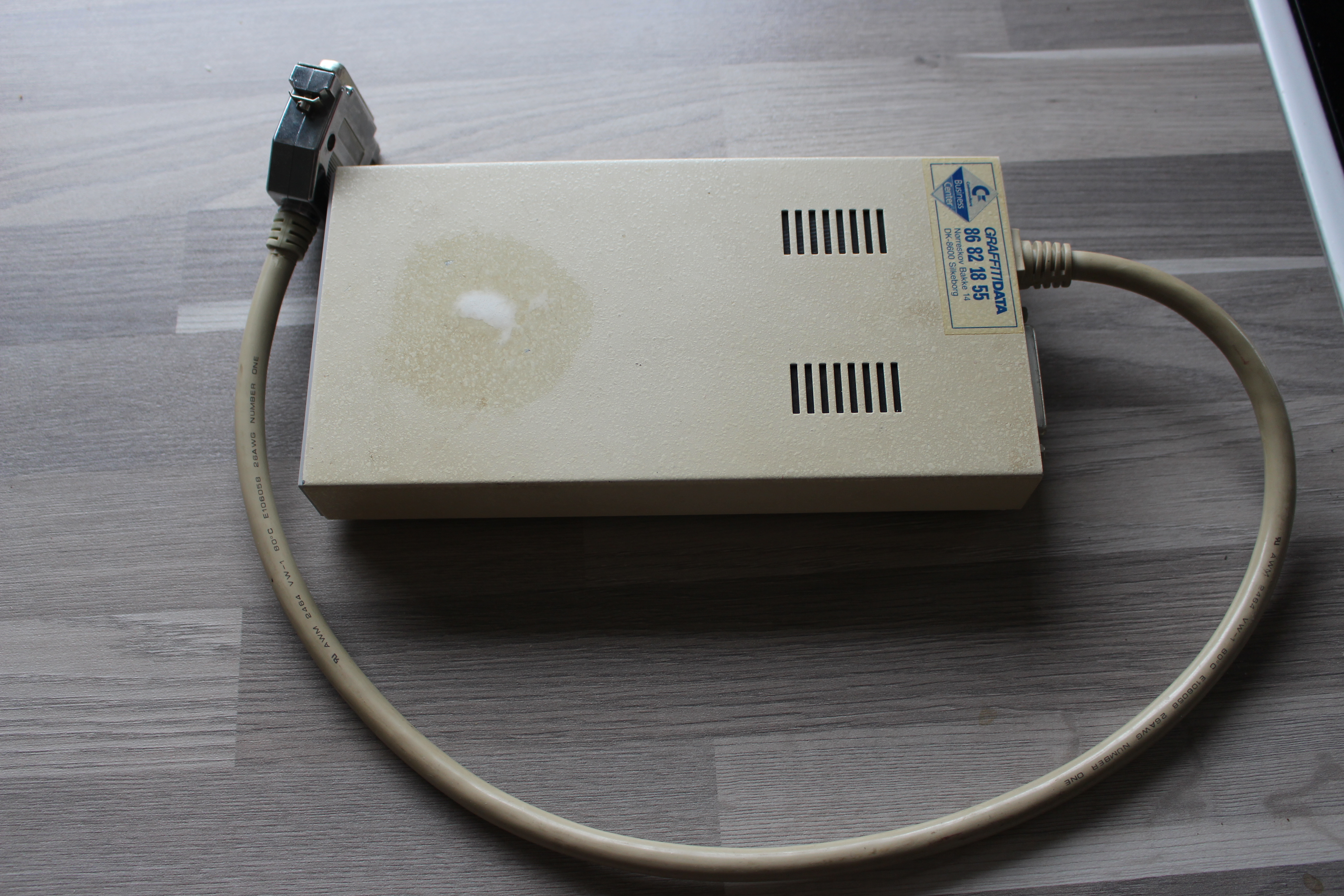
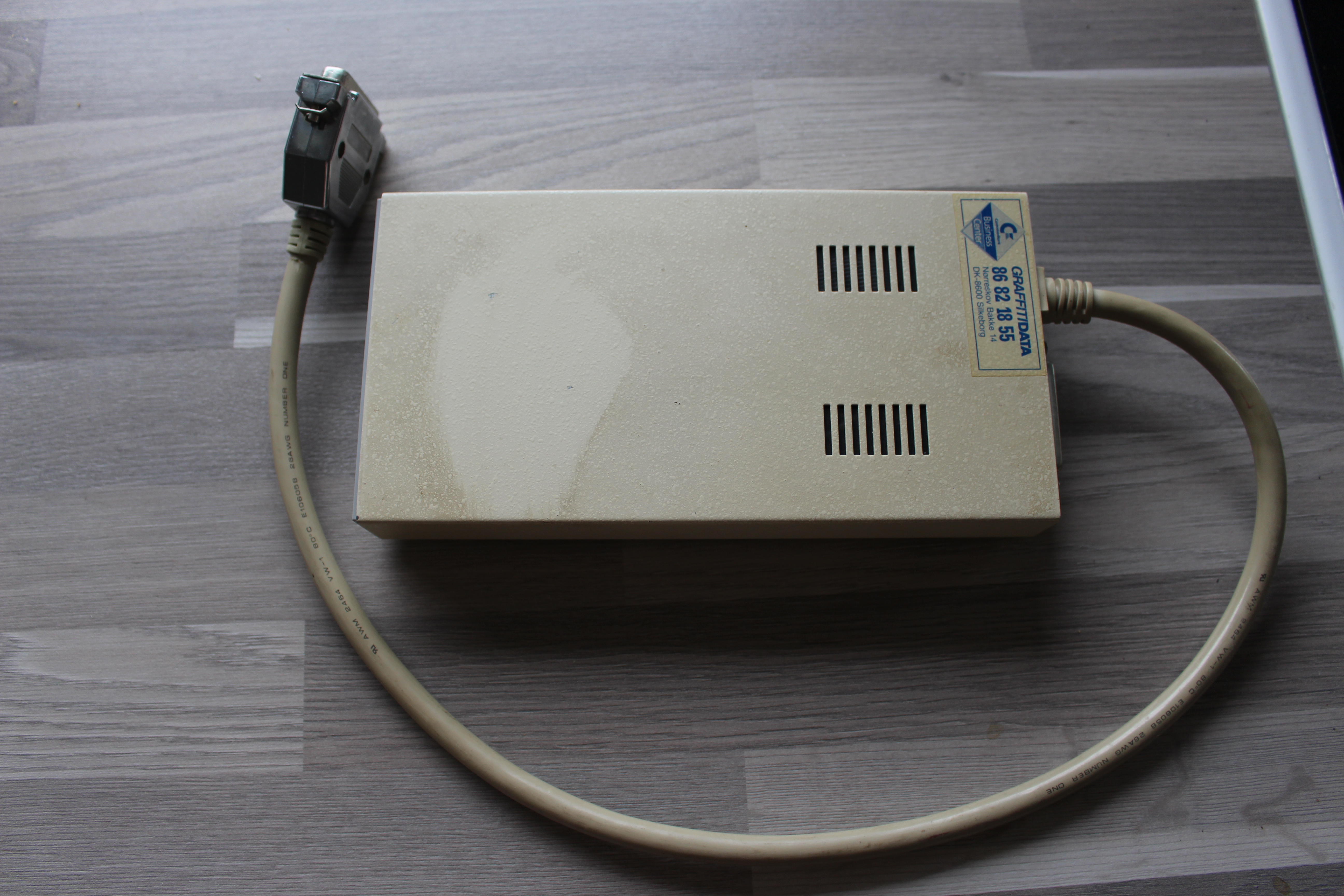
After replacing the floppy drive with the GOTEK I noticed how dirty the enclosure was.
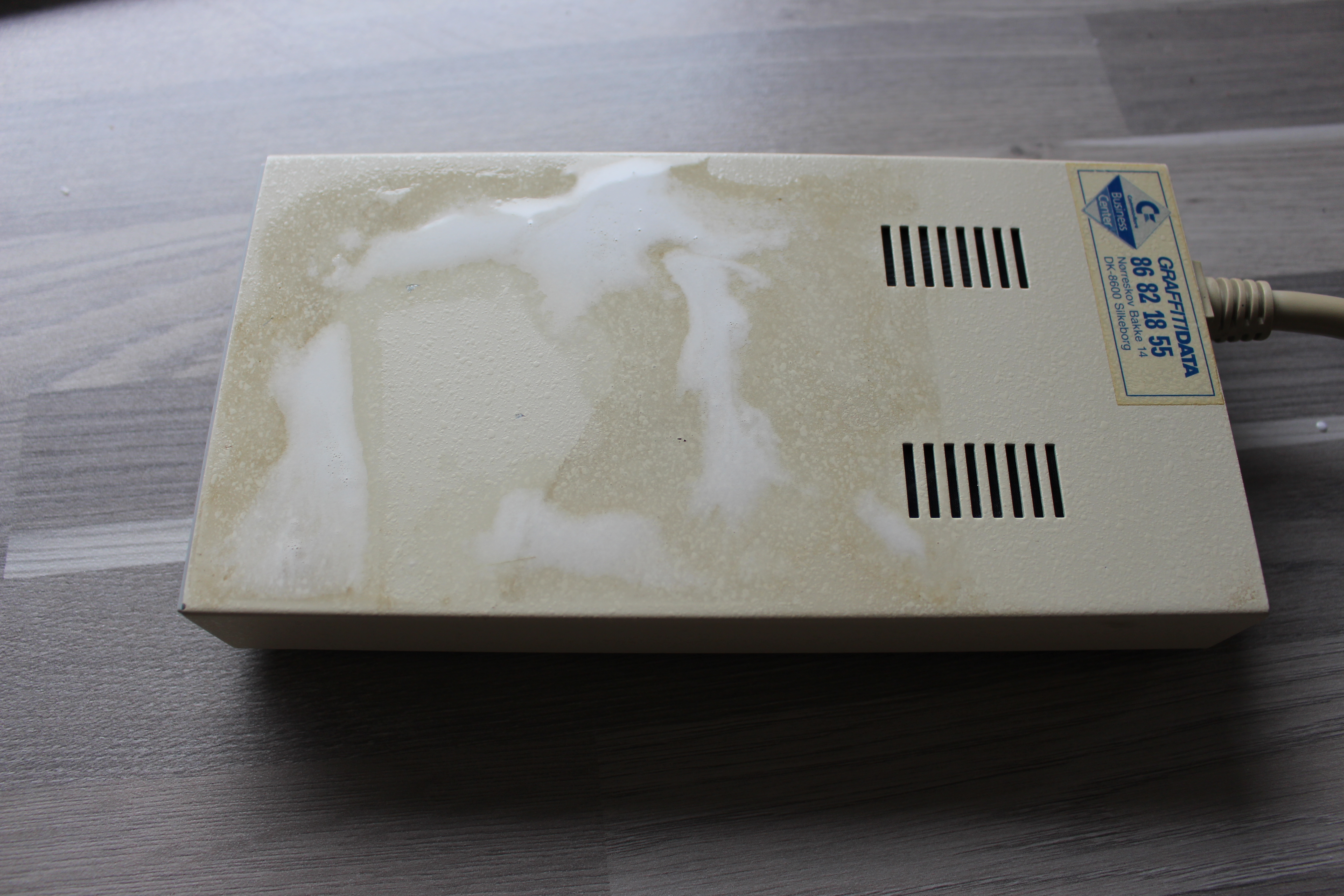
Foamclean to the rescue. The pictures will speak for themselves.
For all support about the GOTEK drive please ask in Hervé’s site.
If you live in Denmark, I can assist in flashing the firmware if required, but I’d suggest that you learn to do that, so you can upgrade the drive when a new firmware comes out.
No it really isn’t that hard flashing this yourself.
And a word of caution. Remember that Hervé was the one who created this firmware. He get’s nothing from any of the guys selling these drives preflashed with the Amiga firmware.
There are quite a few guides on the net, how to replace an existing rechargable battery with a coin battery. Targeted mostly for big box Amiga’s and accelerators, but this can also be used for other similar replacements.
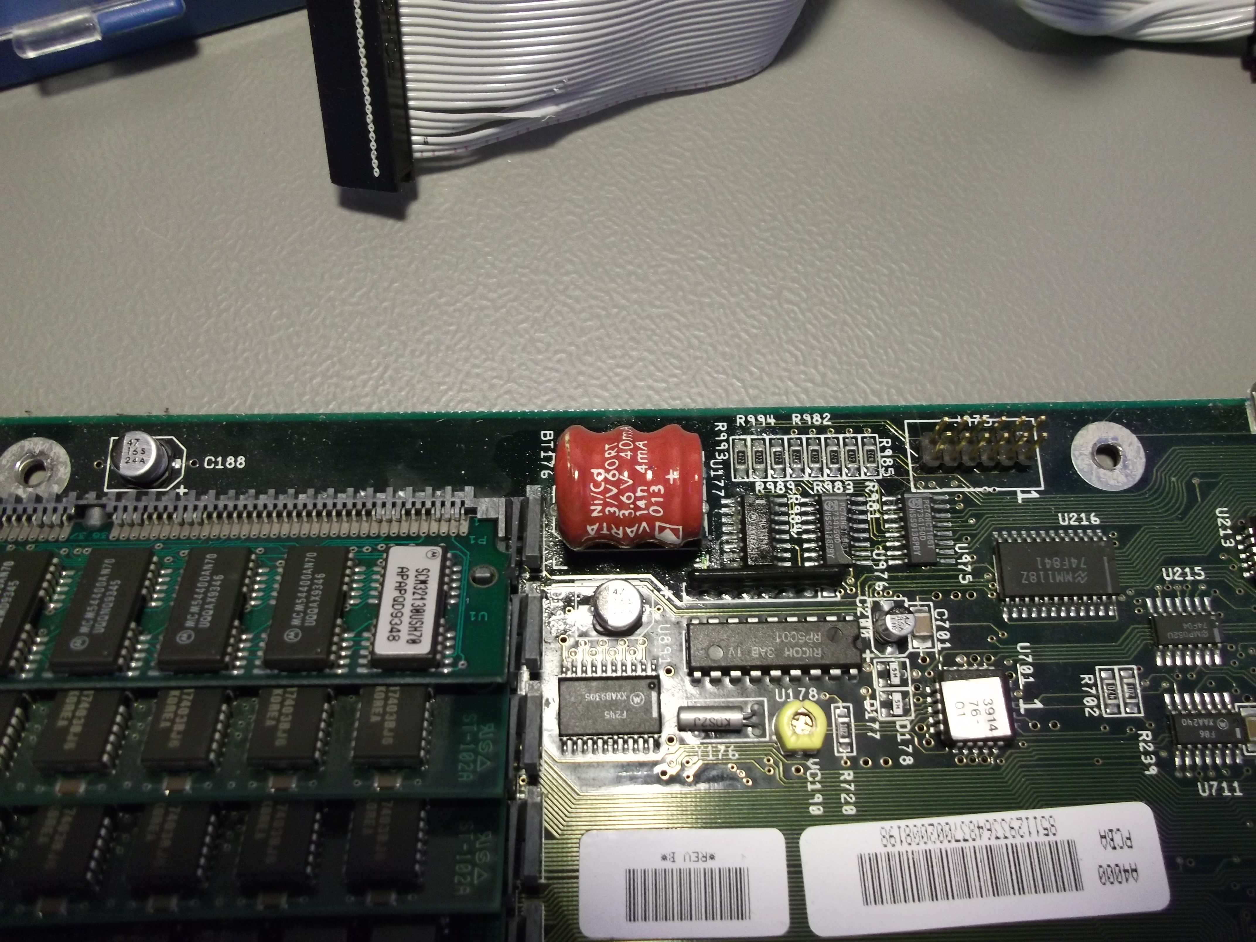
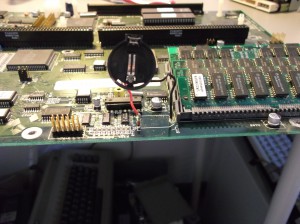
You all know it’s neccessary to change the rechargable battery. If you don’t I’ll tell you why: the battery contains what is commonly mentioned as battery acid, though for these batteries it’s base. Regardless it corrodes the electronics so the battery needs to be removed and the affected area needs to be neutralized. The battery can be removed by using cutters (be careful not to damage the PCB) or just desoldering it. A wash with either lemon juice or vinegar can be neccessary if the battery has leaked. Just drop some lemon juice/vingar and scrub with i.e. a toothbrush. Remove the liquid and wash with either water or isopropyl alcohol.
Before removal.
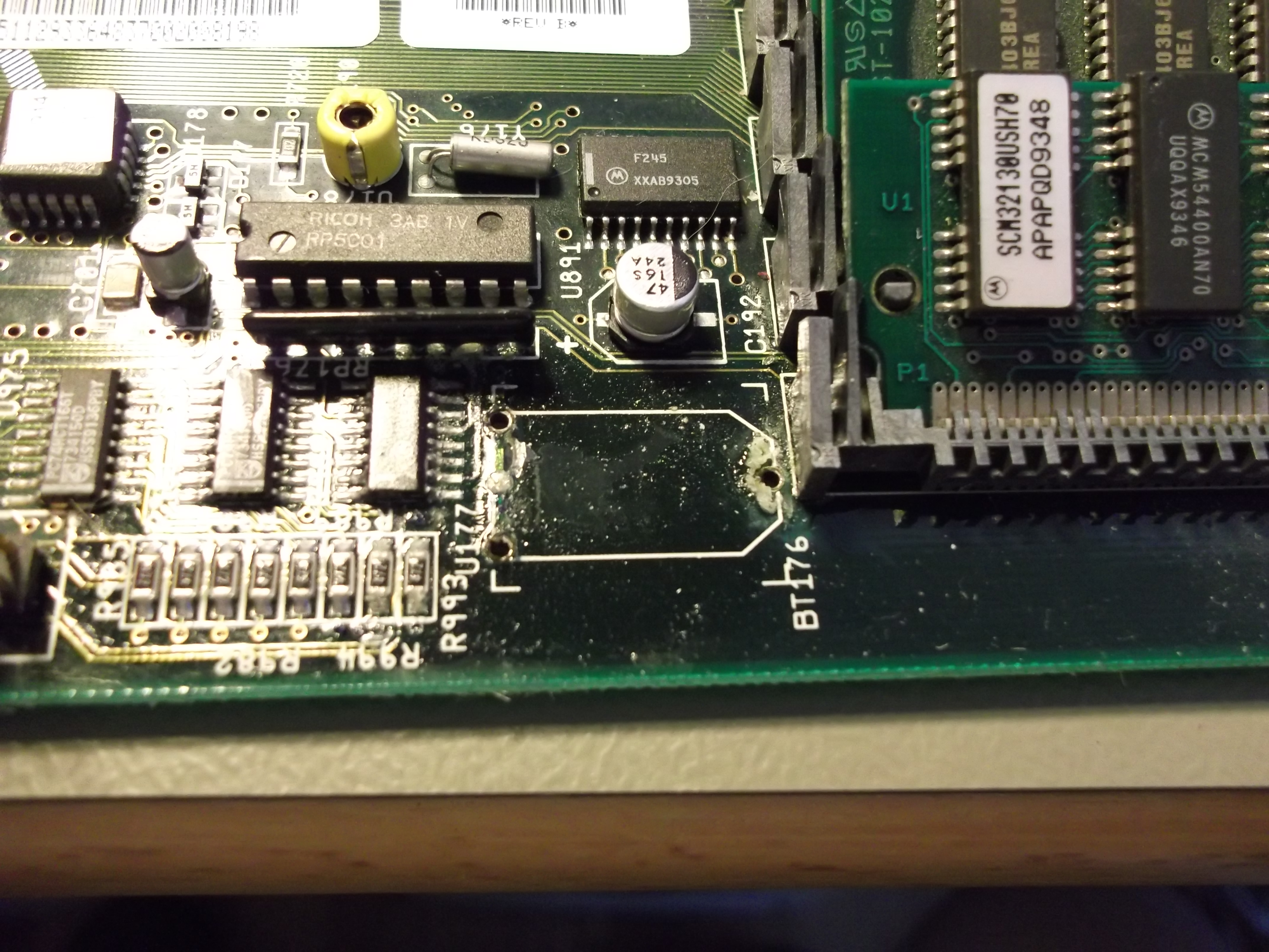
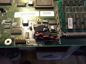
After removal, some area has been damaged, but luckily not much.
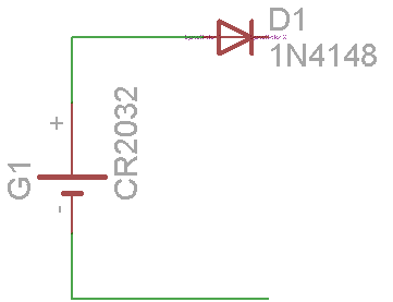
If you’re going to replace with a coin battery like the CR2032, which are quite common these days, you’ll need to add a diode to prevent recharging of the battery with 5v.
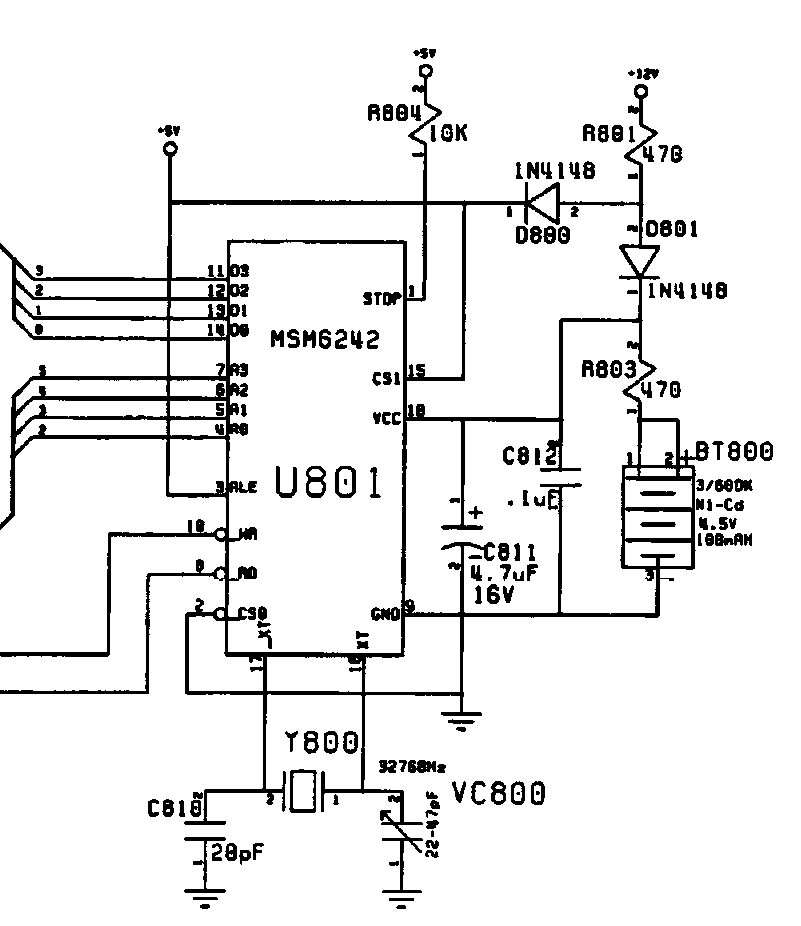
The drawing below should explain it all.The schematic on the new battery.
How it needs to be soldered, plus is to the right and minus is to the left.
Some diode theory 101:
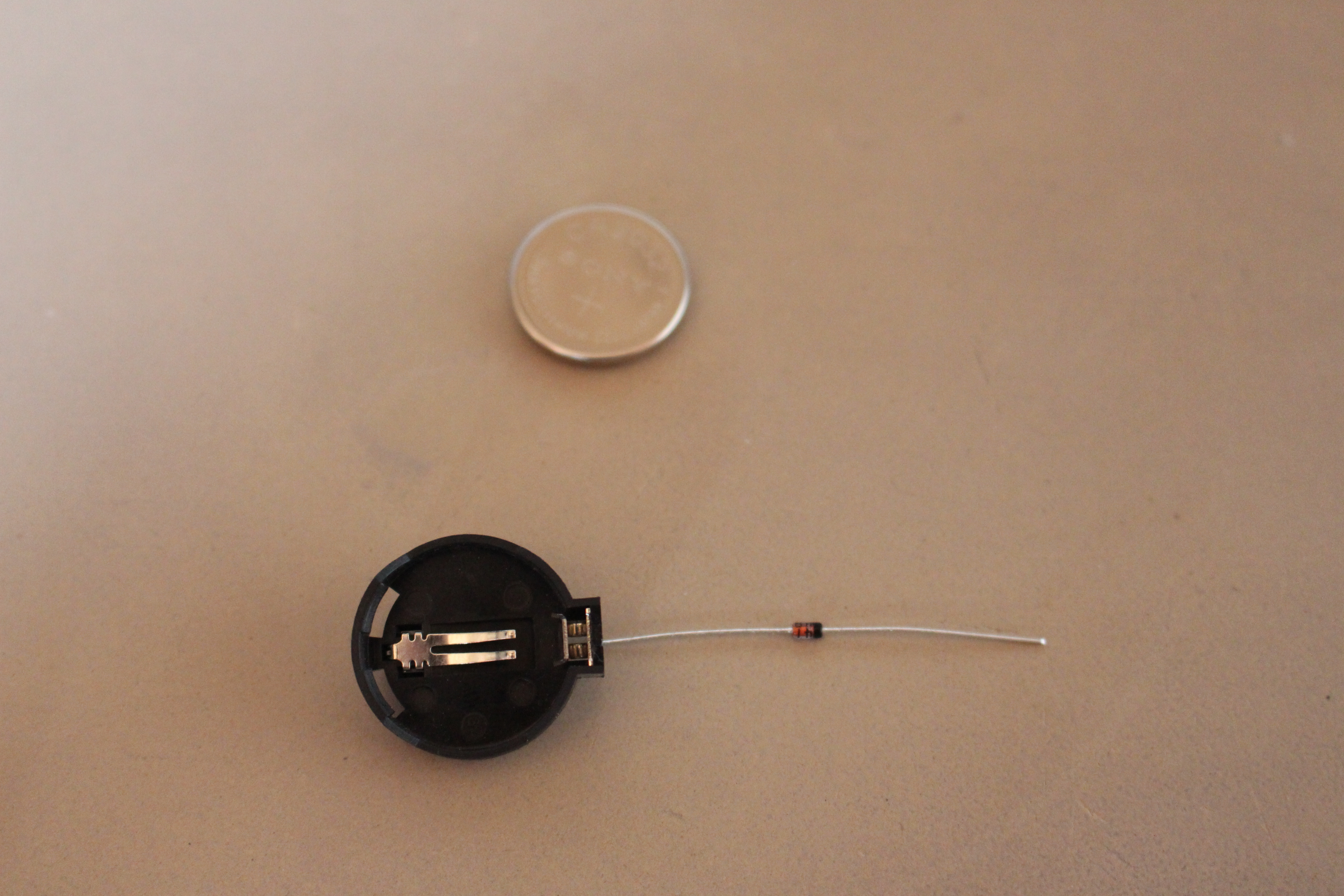
Notice the black ring on the diode, this should be to the farthest side away from the coin battery. Notice the same “ring” on the schematic, that lone vertical dash, thats how you identify which is which. The left side here on the drawing is called anode, and the right side is called cathode. If you turn the symbol 90 degrees CCW, the symbol almost looks like an A, and from the other side it looks like a vertically-mirrored K (just pronaunce the cathode as kathode).
The cathode blocks all the voltage (to a certain degree) that lies on the kathode, whereas the voltage that lies on the anode passes on to the cathode, though loosing around 0.6-0.7 volts.
This way we prevent 5v that’s used to charge the old battery to also charge the non-rechargeable CR2032 battery.
It’s hard to see on this pic, but the black wire extended from the red is a diode all wrapped in a shrink tube. The solder pads here have been dripped with hotglue to prevent shorts.
On this schematic taken from the Amiga 2000 schematics, the battery we’re replacing is in the lowest, rightmost corner (BT800). Looking up the Datasheet of the MSM6242 real time clock, the lowest voltage for battery backup is 2v. So with the CR2032’s 3.3v minus the 0.7v (= 2.6v) the battery supply is still enough to sustain the real time clock.
Components used: CR2032 socket, 1n4148 diode.
You can use most regular diodes like the 1n4141.
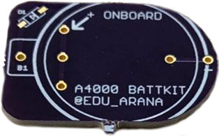
Update: 2019-04-02
Araranet has created a small pcb which works as a drop in replacement for the old barrel batteries, The A4000battkit, ready for sending to pcb companies like jlcpcb.com.
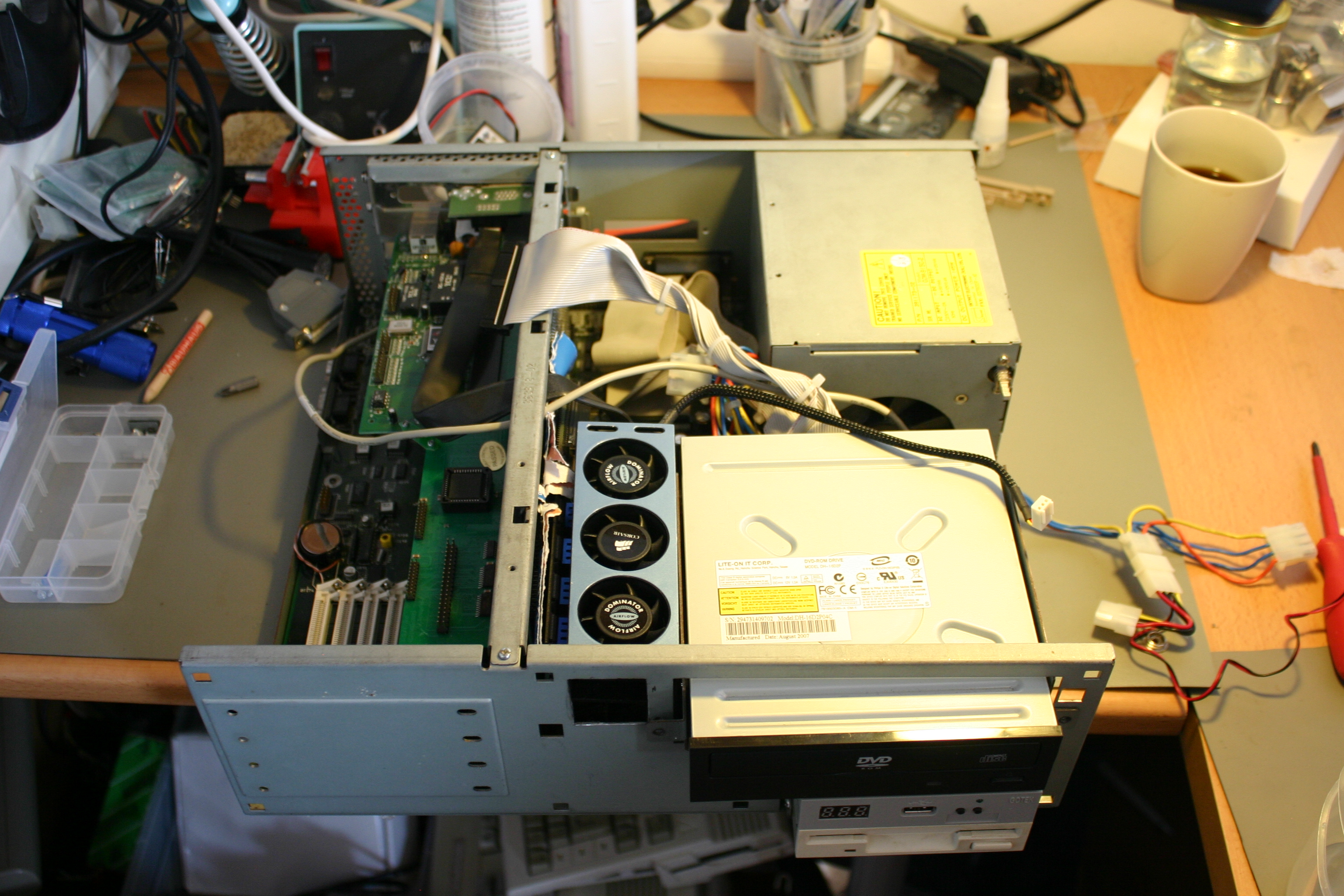
After using my Amiga 4000D with CyberstormPPC and CyberVisionPPC for several hours, the enclosure got quite warm to the touch. This made me a quite anxius as I don’t want the hardware to die because of heating.
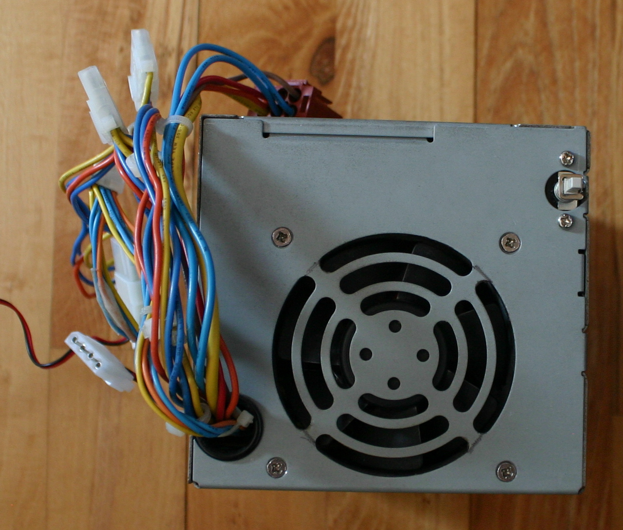
I found out that the PSU fan pulled air from the back into the enclosure, I wonder if that was by design or someone having flipped the fan in the wrong direction. This needed turning so it would transfer the hot air from inside through the PSU to the outside of the enclosure. While at it, I could improve the flow a little, and reduce the noise of the fan. I don’t want to use a lower voltage with a lower fan speed, this is due to I prefer to keep my hardware cool and in good order.
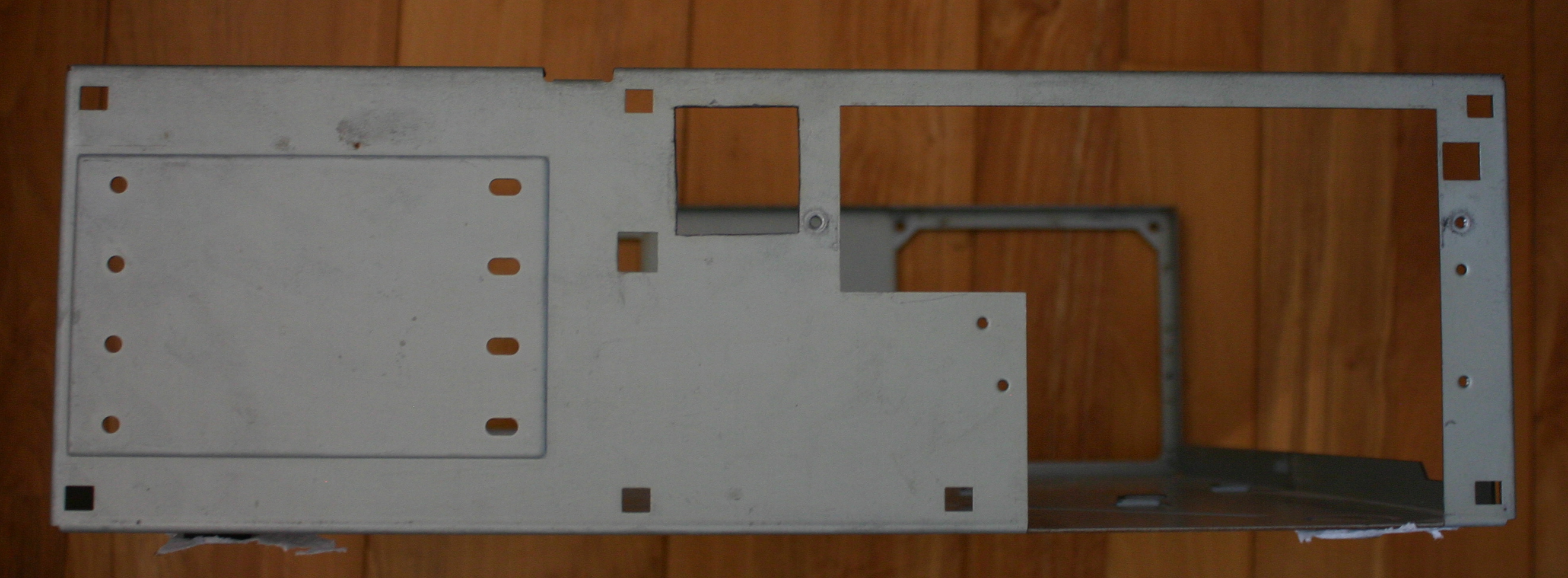
Taking evertything apart is easy, so I find no need to explain how to do that. The before picture of the PSU. You can vaguely see my pencil marks where to cut.
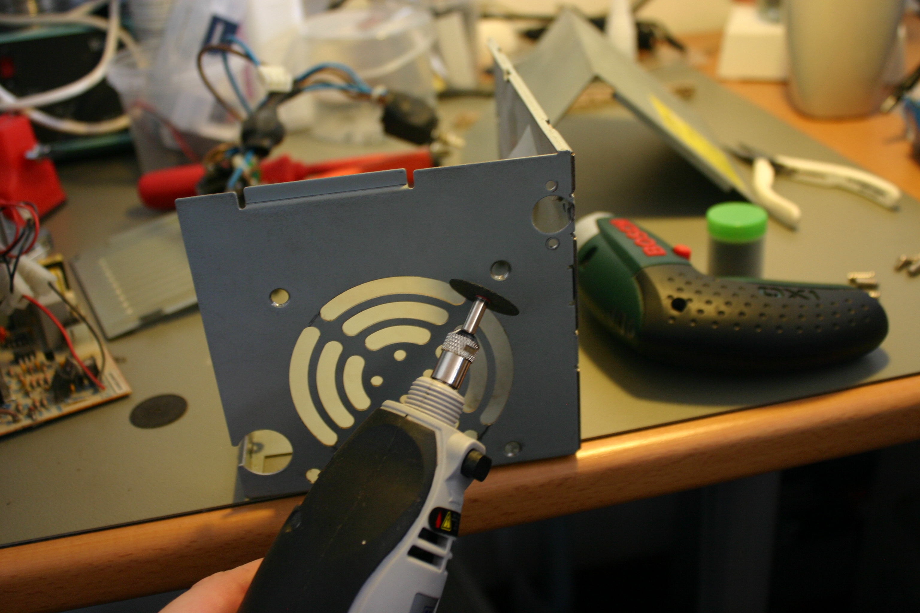
Time to get busy with a dremel and a cut-off wheel.
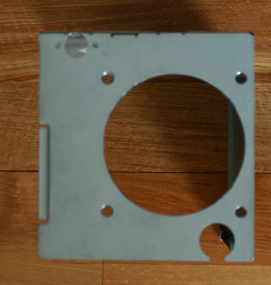
Pretty good result.
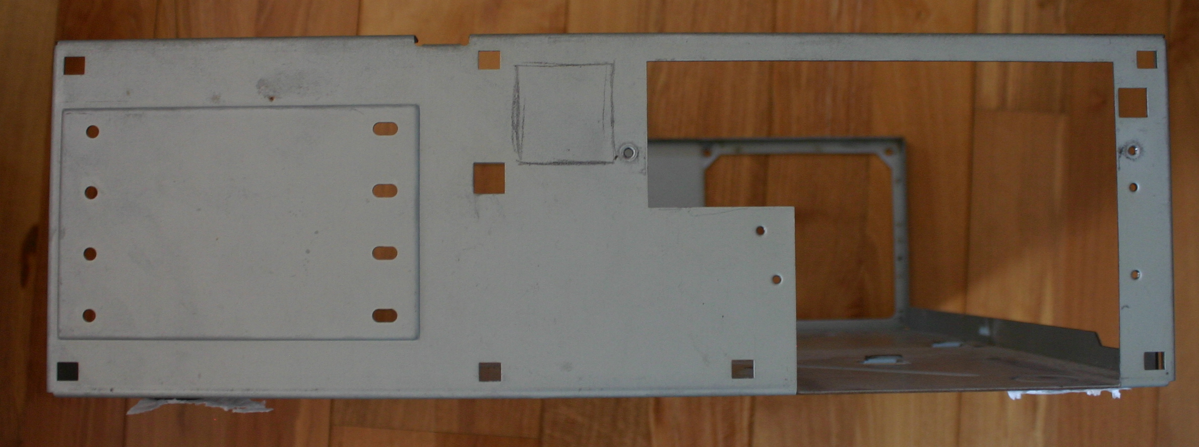
The area where I can pull air from the front isn’t that large, I still want to keep the holes for the different parts, like to fasten the external drive bay, putting wires through the hole, and the front bezel in the middle top.The dremel is a great tool for this, and mine isn’t even an original one, but something cheap bought in an Aldi store.
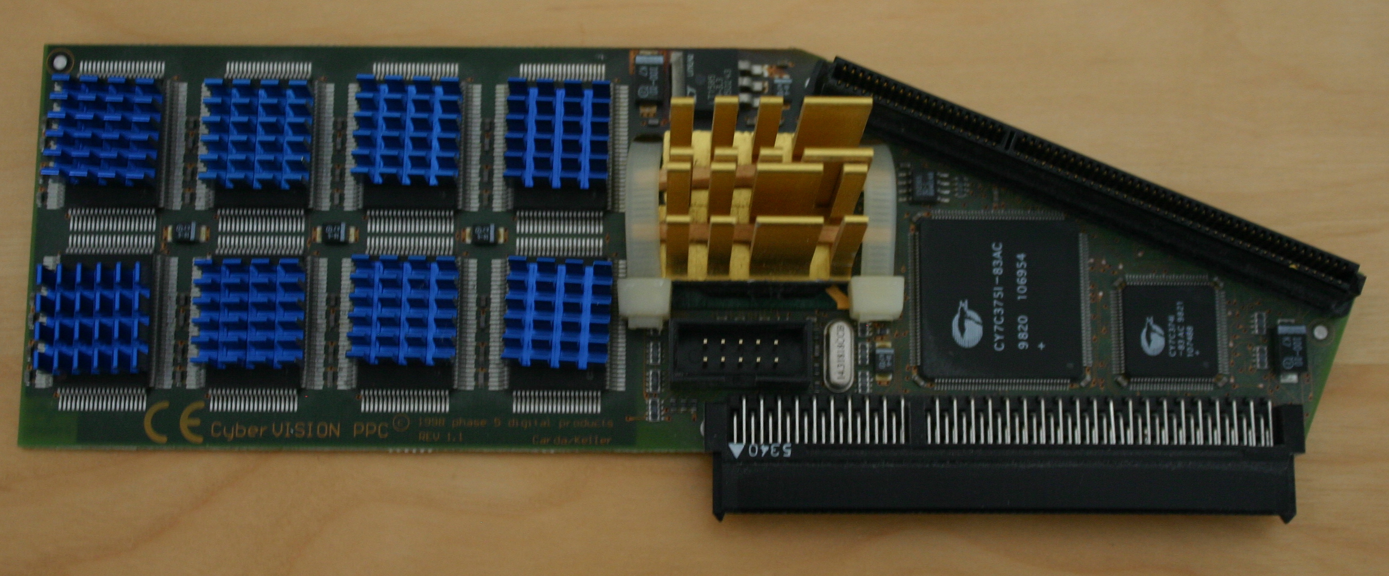
Time to add heatsinks to the CyberVision. I recieved this one with the GPU mounted heatsink, no need in changing that. But I added the heatsinks on the ram chips, these I got off eBay. I added the heatsinks long before this project, and eventually that was a mistake as they are mounted in the wrong direction for best cooling. Oh well, they work better than with no heatsinks.
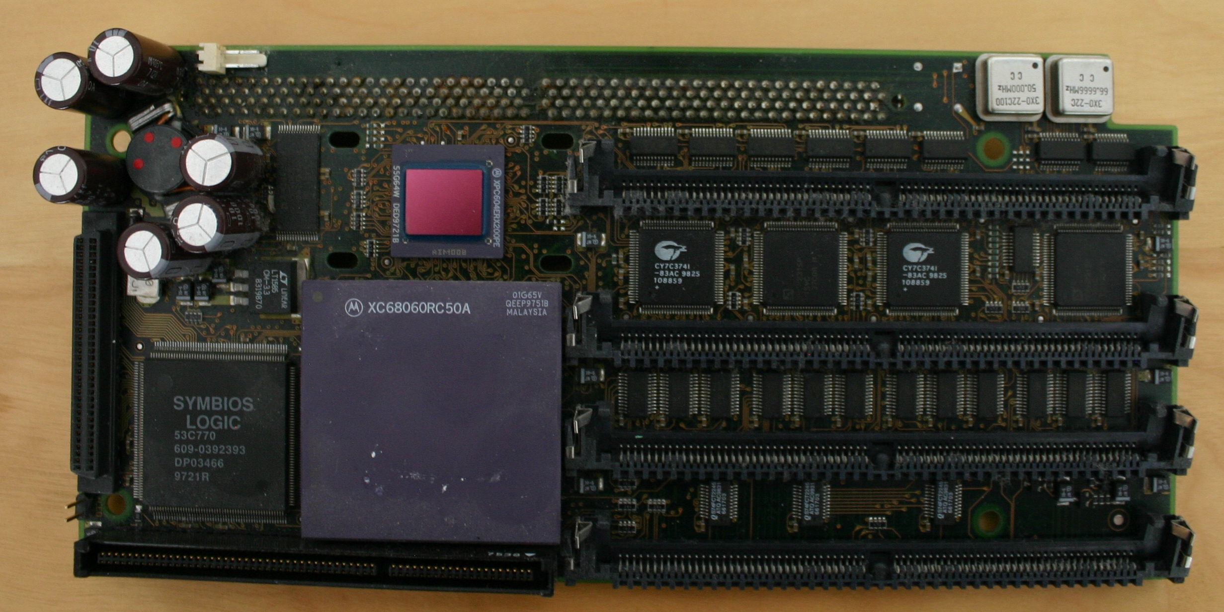
For some reason I didn’t take a picture of mounting a heatsink on the 68060 cpu. I used an old heatsink from a 80486 cpu, added compound paste, wiped off the corners and used LocTite glue on those corners. I also added some paste to the PPC CPU before reattaching the heatsink and it’s fan.
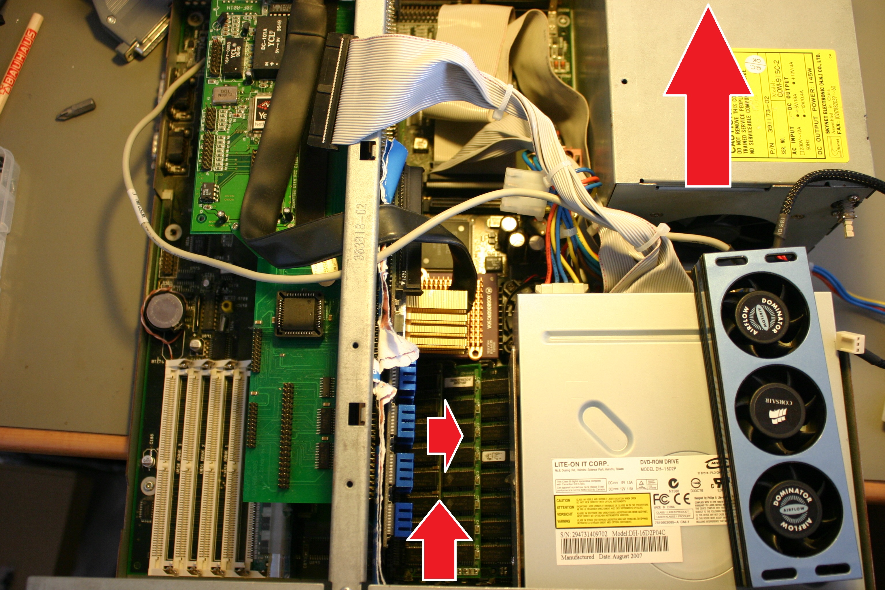
I had a stick of fans from some Corsair ram for my PC, these I soldered a molex connector and gave it 7v (using 5v as ground and 12v as reference). The flow of air is marked with the arrows. In through the front, down on the Cyberstorm ram (you might be able to spot the heatsink on the 68060 CPU if you click on the image to see the full size), and out through the PSU.
The (almost) finished project. It’s not perfect, but it works pretty well. I’m still looking for a better way to attach the ram coolers, acryllic glass comes to mind. After several hours of usage the enclosure is now still cool to the touch, only the area around the PSU is warm, but not as warm as it was before.
One of the problems with the Commodore and Philips monitors models C=1084, C=1084S, C=1081 etc, CM8833, CM8833-II, is the power switch is no longer able to be “stuck” in it’s ON mode. These are generally easy to replace if one can find a replacement unit.
I recently got some power switches off a guy from Amibay, these aren’t the exact same models as the ones used for the monitors, but they are still useable.
The switch is originally produced by Preh and is called ME5A, but there are quite a few models of these, and they aren’t written on the switch itself. So if you hunt down the switches, make sure you atleast get to see if the pins are meant for PCB soldering or just wires. The ones I received are solderable into the PCB, thus also useable for wires.
The original model number for the C1084S is: PREH ME5A 70060-062 (NS28)
The replacement used here is: PREH ME5A 70060-232 (NS11)
If you know how to use a solder iron, and know your way around cables, this should be easy for you otherwise you should contact a professionel or atleast someone experienced to help you out.
This whole procedure can be done in 10-15 min.
WARNING: the CRT monitors have high-voltage inside and can give you shock if you’re not properly protected or careful. Touch only on plastic.
DISCLAIMER: if you by any means, hurt yourself or your equipment, I can’t be held responsible for any damages done.
UPDATE 2012-12-11 :A (badly made, which was made spontaneously with a smartphone) video showing the CM8833 monitor and how to unplug the 2 wires and access the power switch is shown in the bottom of this article.
Before starting, unplug the power chord, and any other cables attached to the monitor.
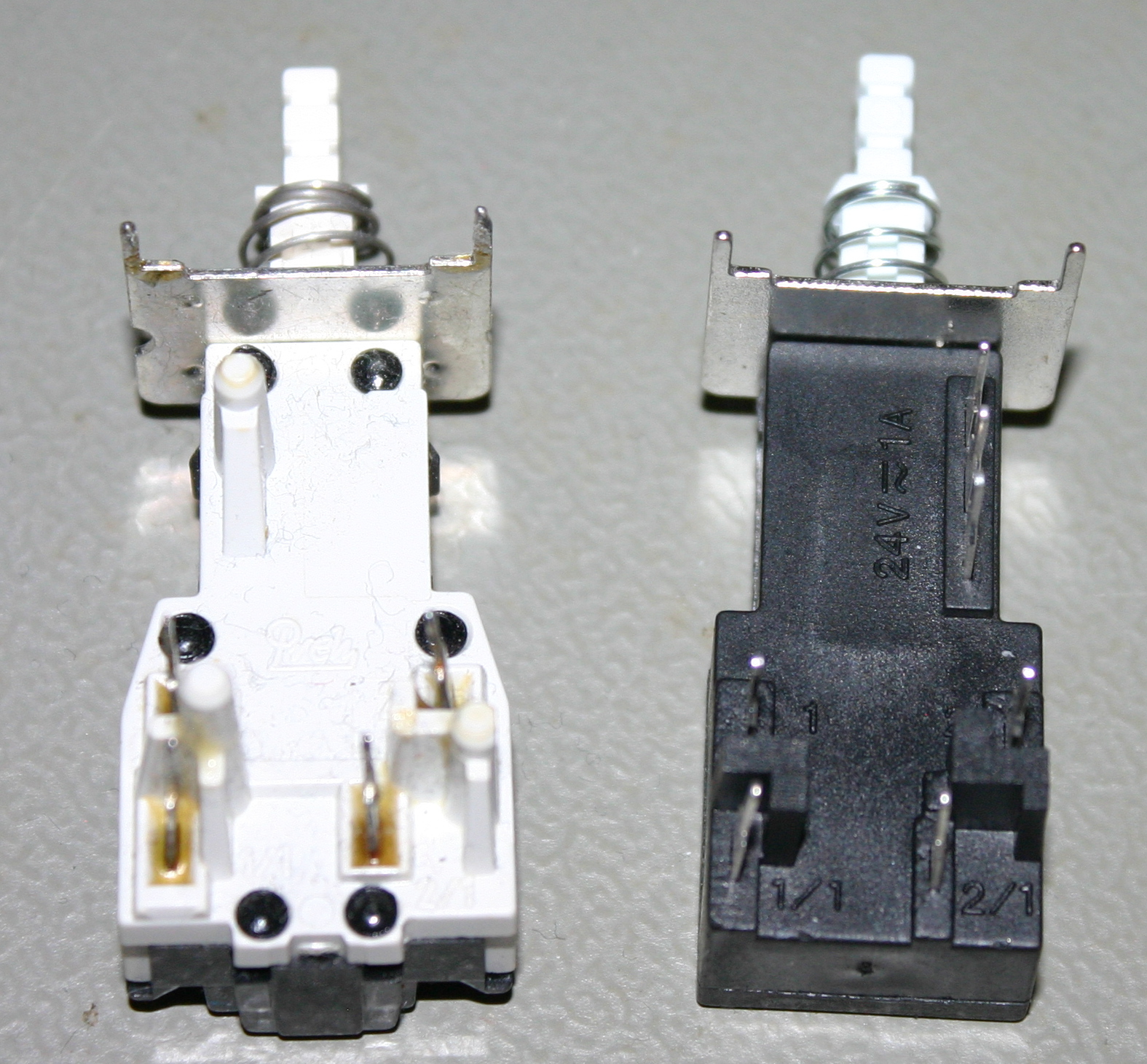
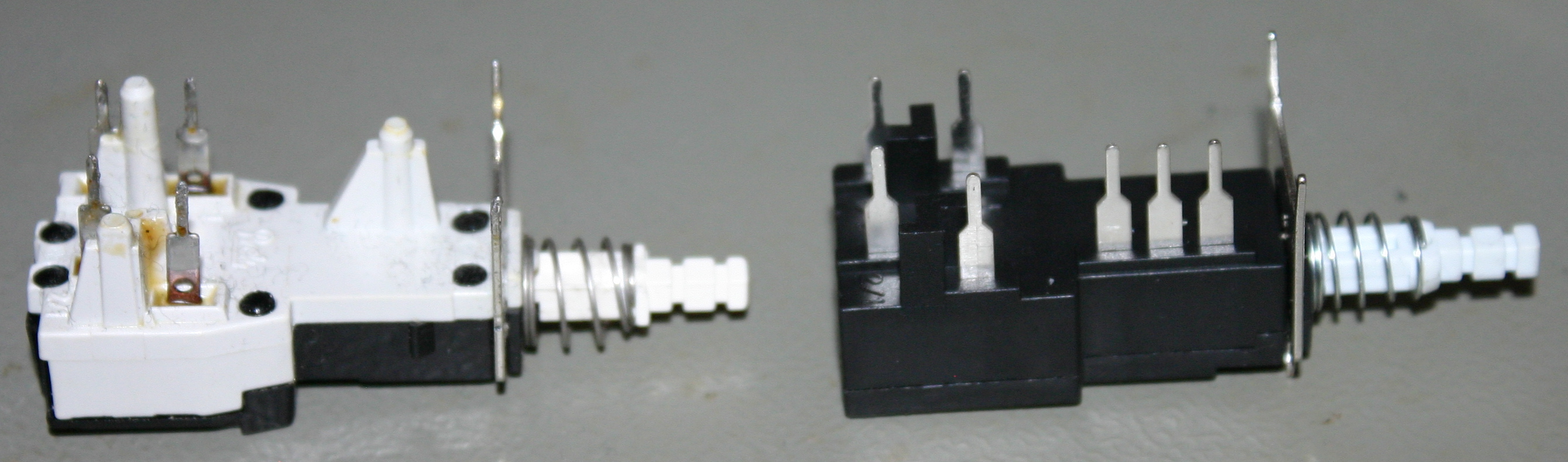
The switch to the left is the original one (from 1084S, I didn’t take a picture of the one from the 1084), and the one to the right is the new one.
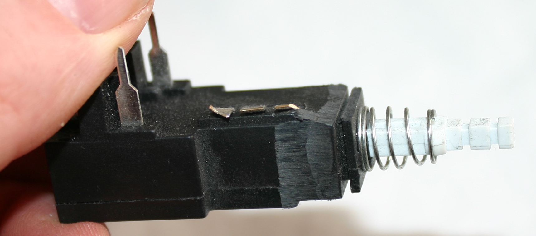
The ones I received here has a few extra pins which aren’t needed for our purpose, so we’ll just cut these pins off.
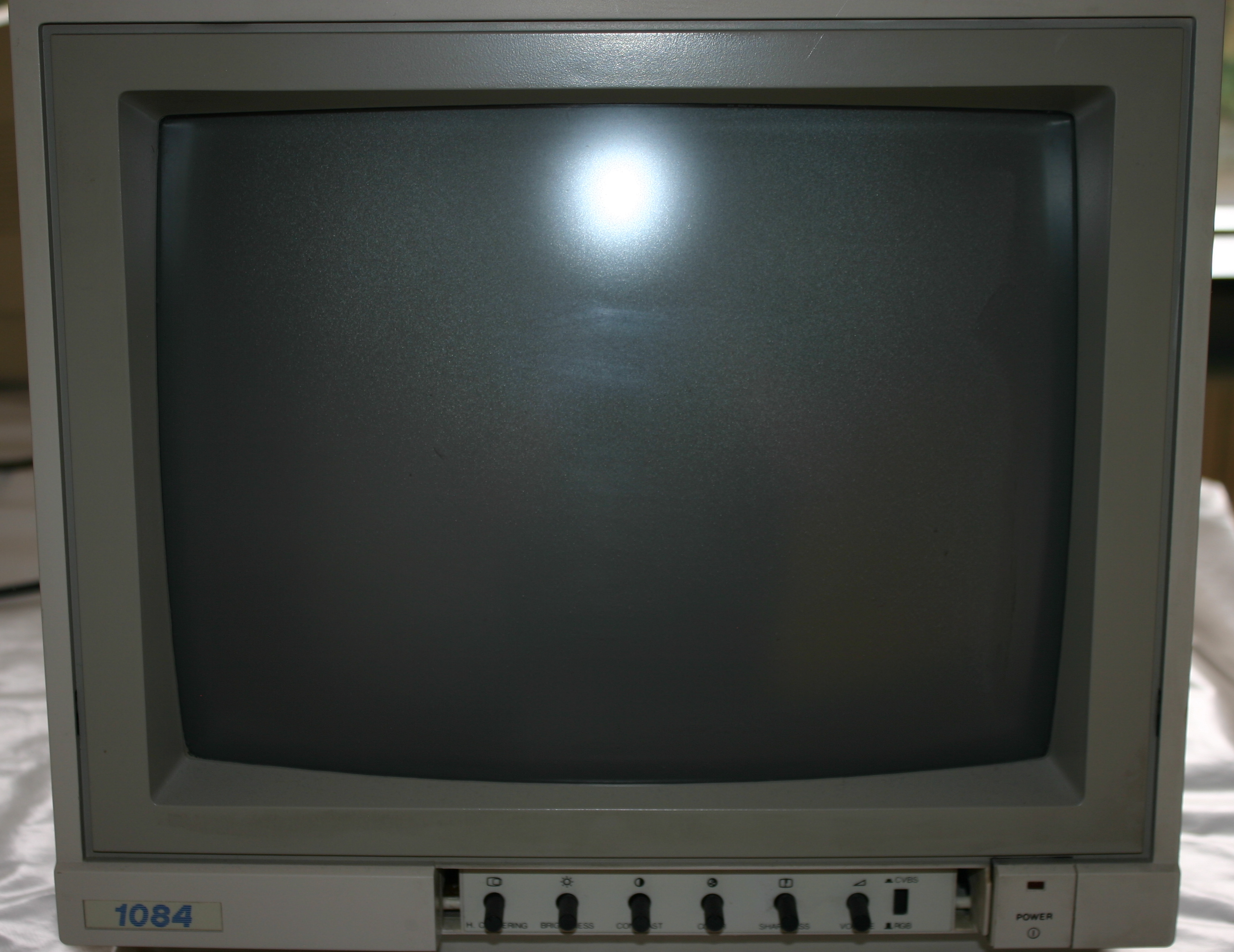
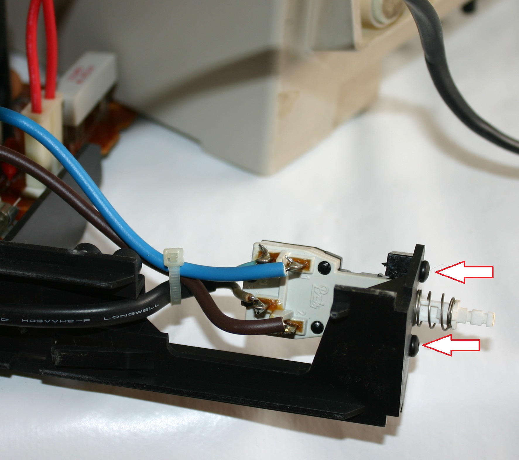
The 1084 Monitor with the power switch in the front.
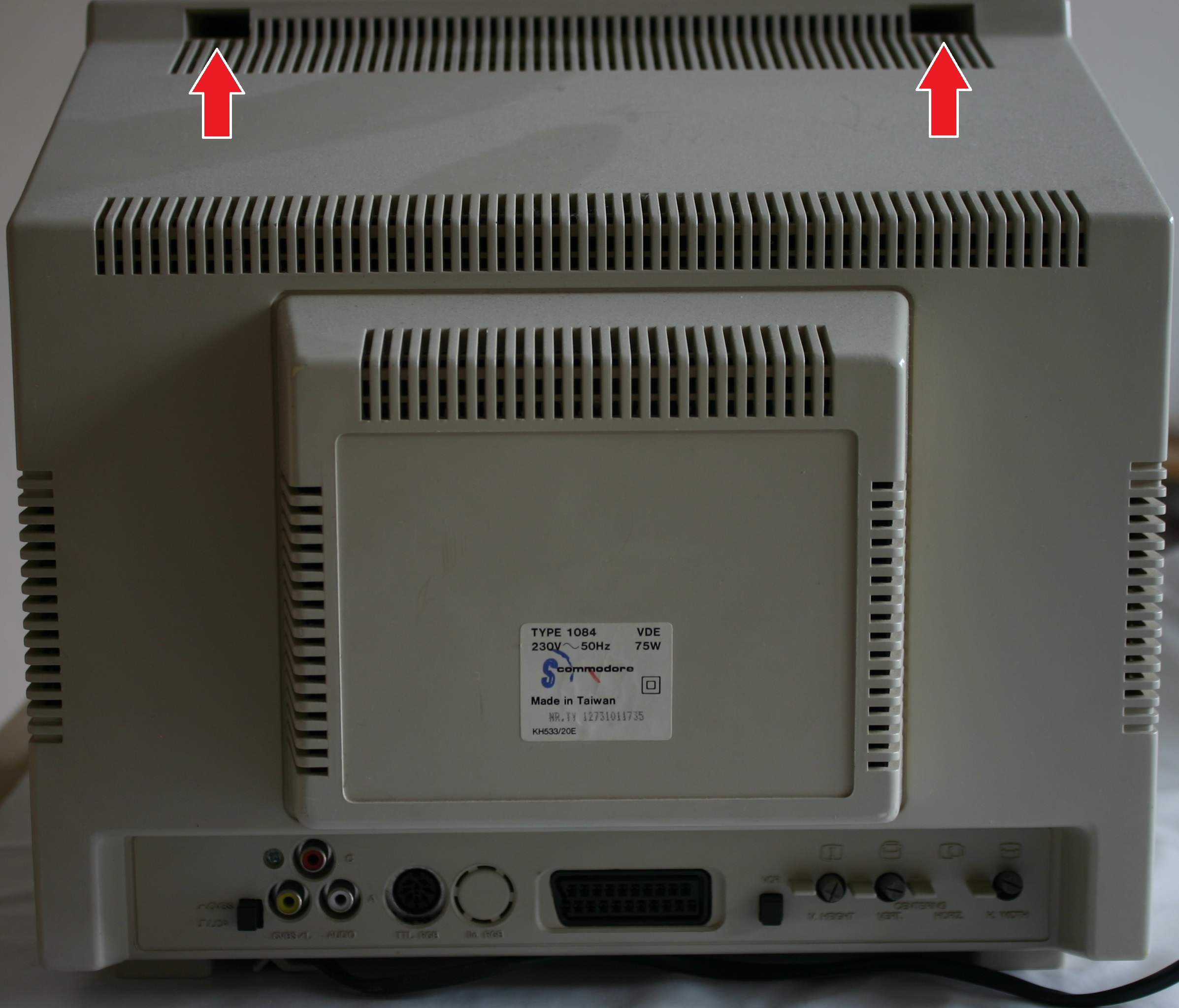
Remove the philips head screws in the holes where the arrows point.
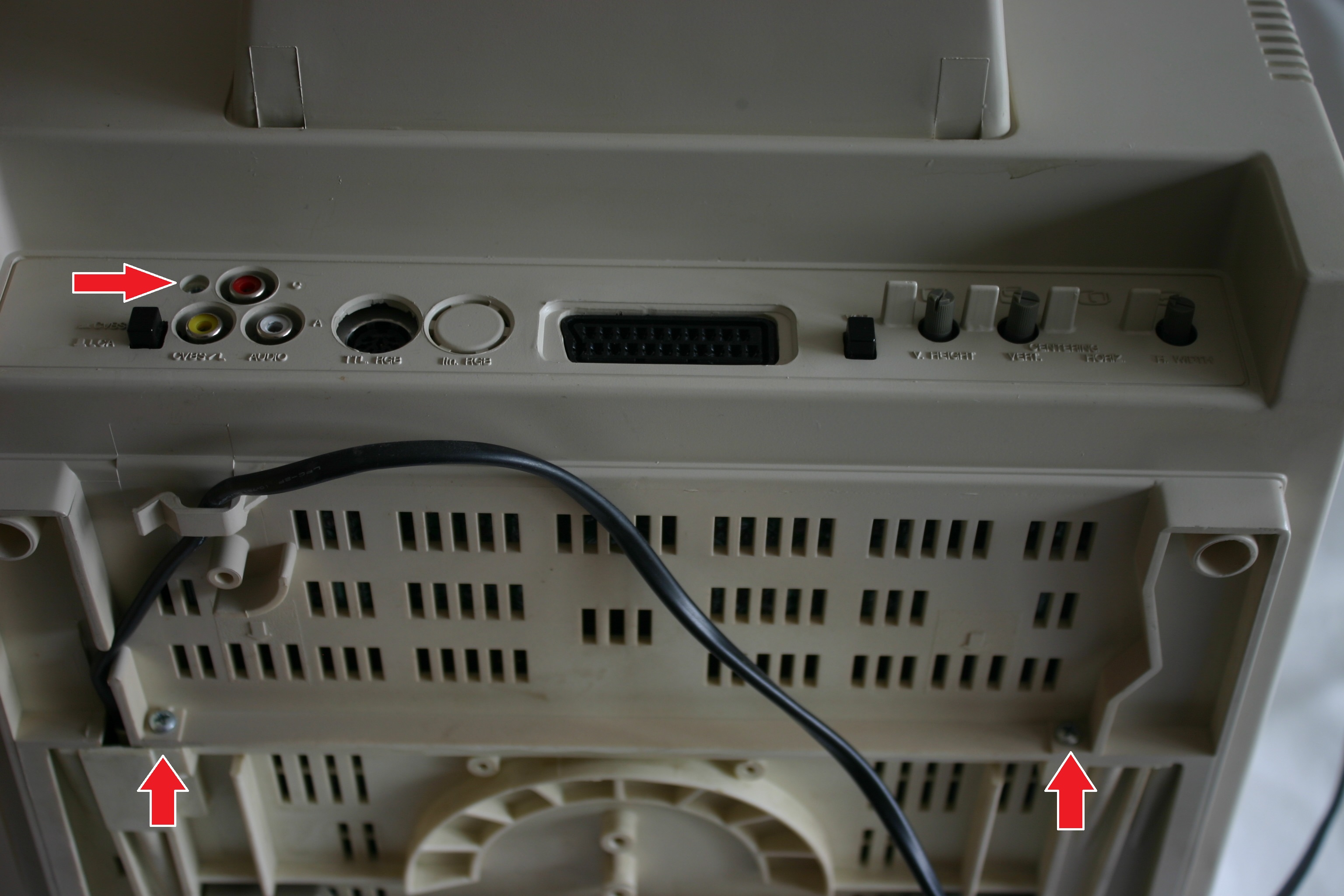
Remove the philips head screws in the holes where the arrows point, remove the 2 in the bottom first before unscrewing the one close to the audio/video output.
Make sure the power chord is removed from it’s holding clip.
Now you can gently slide off the back of the monitor. Be careful not to touch anything not plastic, as you can get hurt.
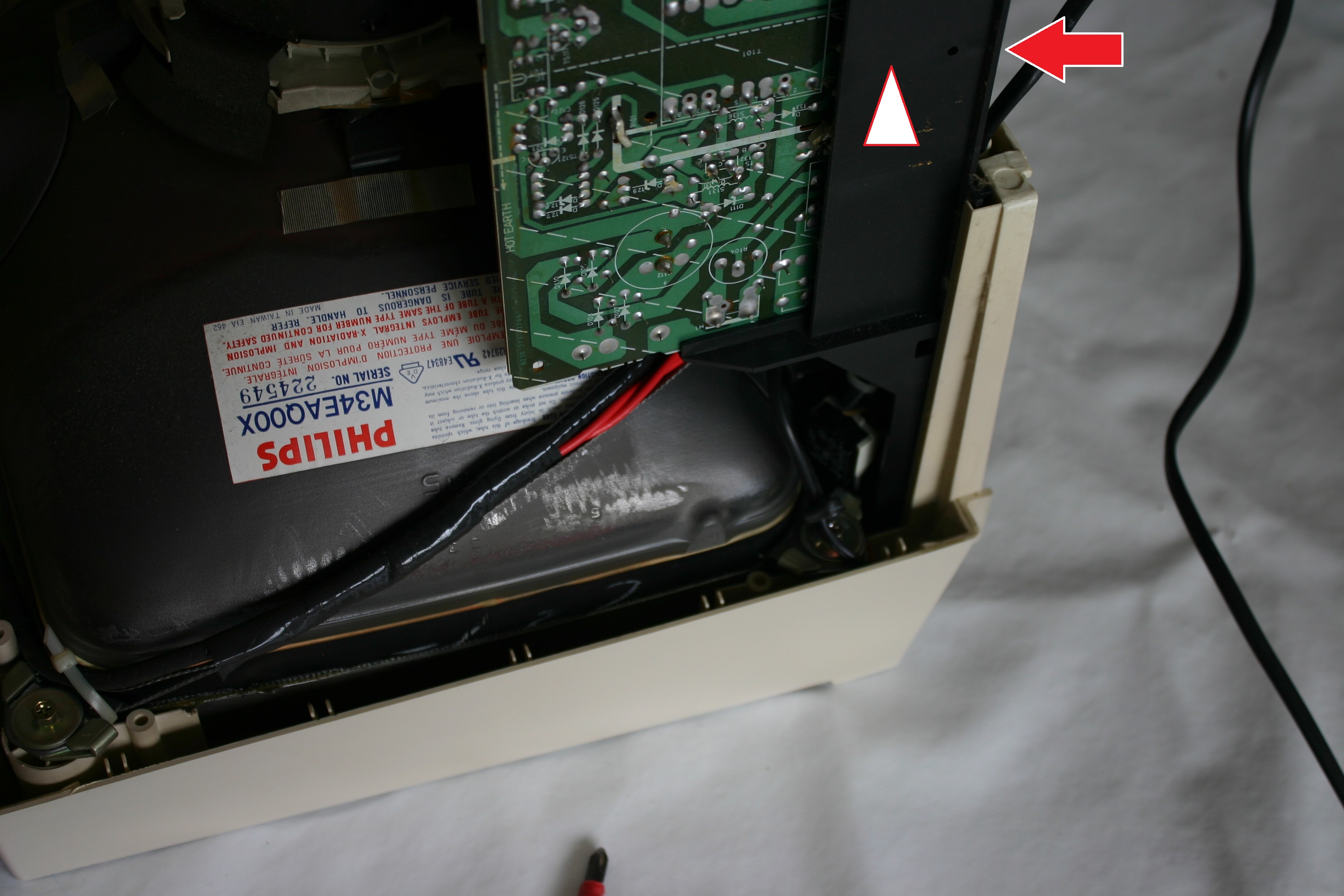
There might be a wire attached inside, to the back you’re pulling off, this wire can easily be removed. Just remember where it was located before assembling again.
There is a small plastic tap that needs pushing around the area where the red arrow is pointing, when that is pushed the small PCB in the plastic can easily slide up.
There is a wire connected to this board, which should be removed before pulling up the PCB.
Now that you have access to the switch, remove the 2 screws, and unsolder the power wires (or cut them, just make sure you cut as little as possible as you need the full length of the wire)
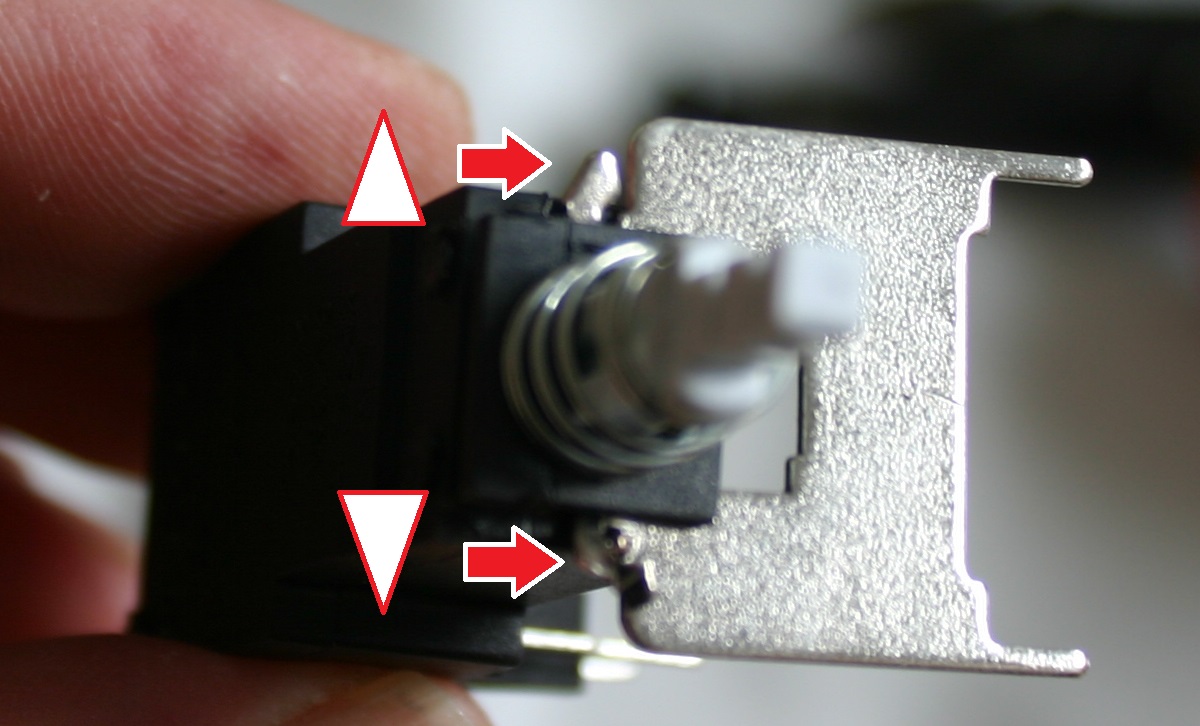
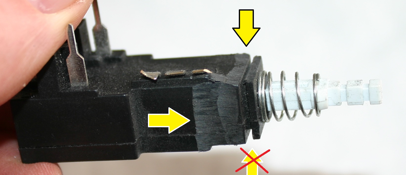
On the power switch I received it had a mounted plate, this can be removed by using pliers bending back the metal locks (white arrows), and gently pulling off the plate (red arrows).
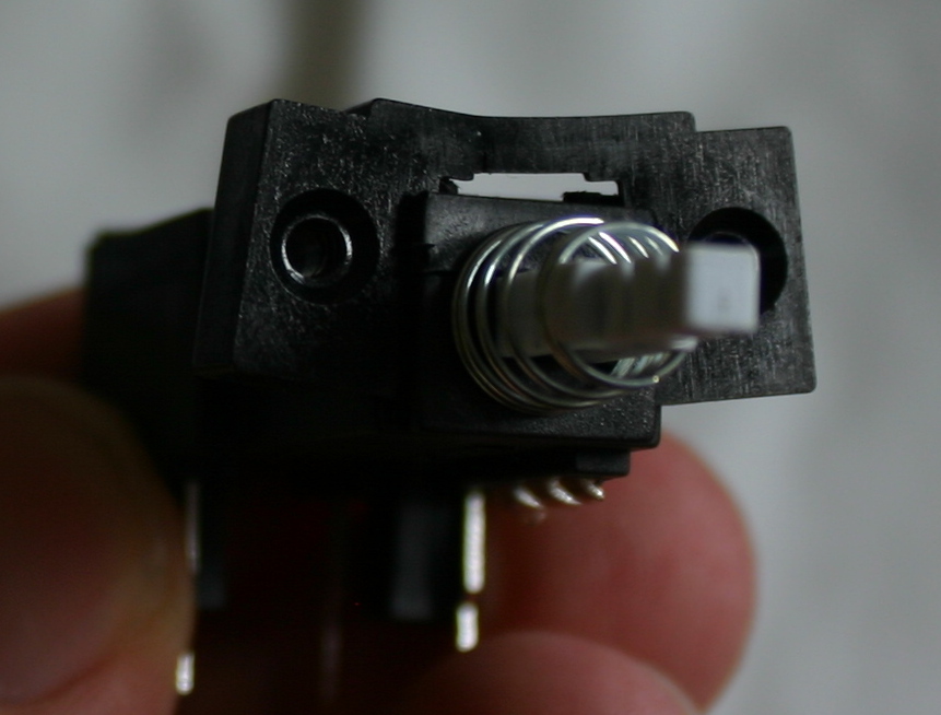
The plastic bracket on the old switch is needed, so gently pull this off.
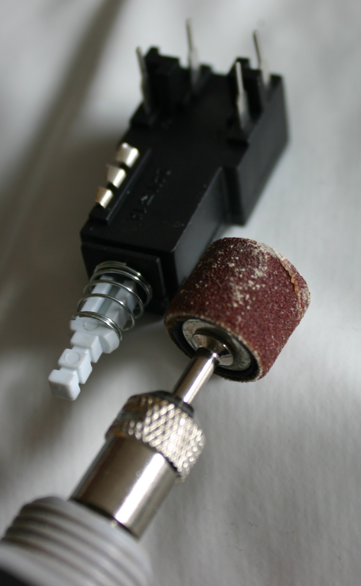
It didn’t fit on the switch I had so I had to do a little sanding.
I used my dremmel to sand down the plastic in the sides and bottom.
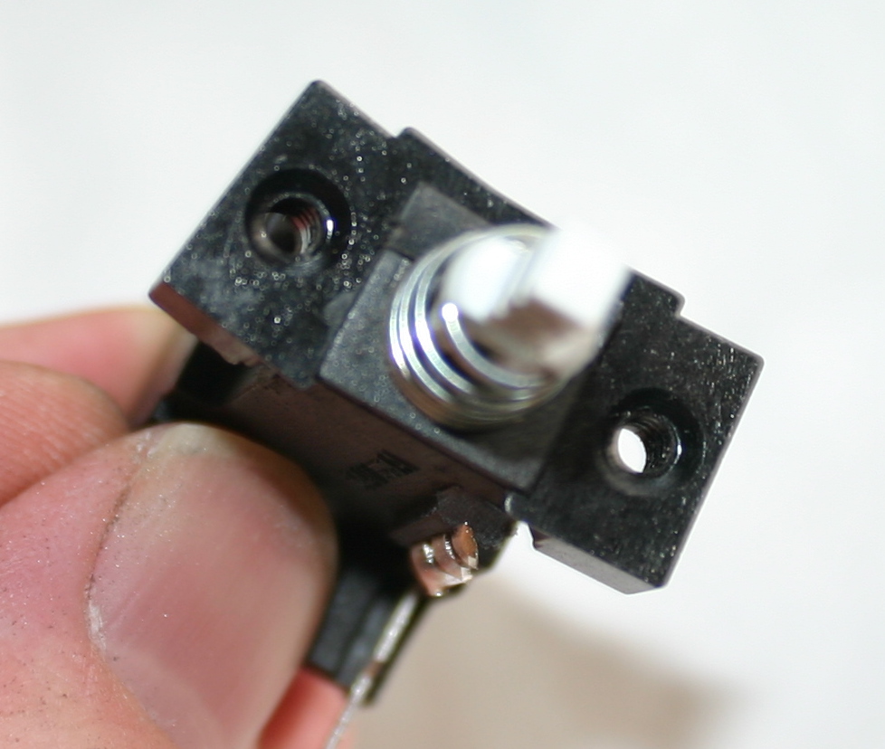
The result looks like this, I had to try mounting the plastic bracket several times before I was satisfied.
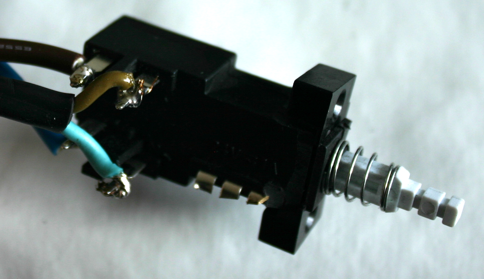
Time to solder the power wires onto the switch. Make sure that you have one set of cables to the back of the switch, and the other towards the front. Brown needs aligning to brown and blue needs aligning to blue. On the picture the cables going to the monitor are soldered to the leftmost pins, brown up/blue down, and the power chord is soldered to the right most part of the switch, brown up/blue down.
All you have to do now is mount everything back the way it was.
Fasten the switch to the plastic slider.
Slide the plastic slider into place.
Reattach the cable that was removed earlier.
Reattach the cable from the plastic casing back.
Slide the pack of the monitor into place.
Attach the 5 screws.
And you’re done.
A video showing the Philips CM8833 monitor (which is almost identical to the C= 1081) and how to access the power switch.

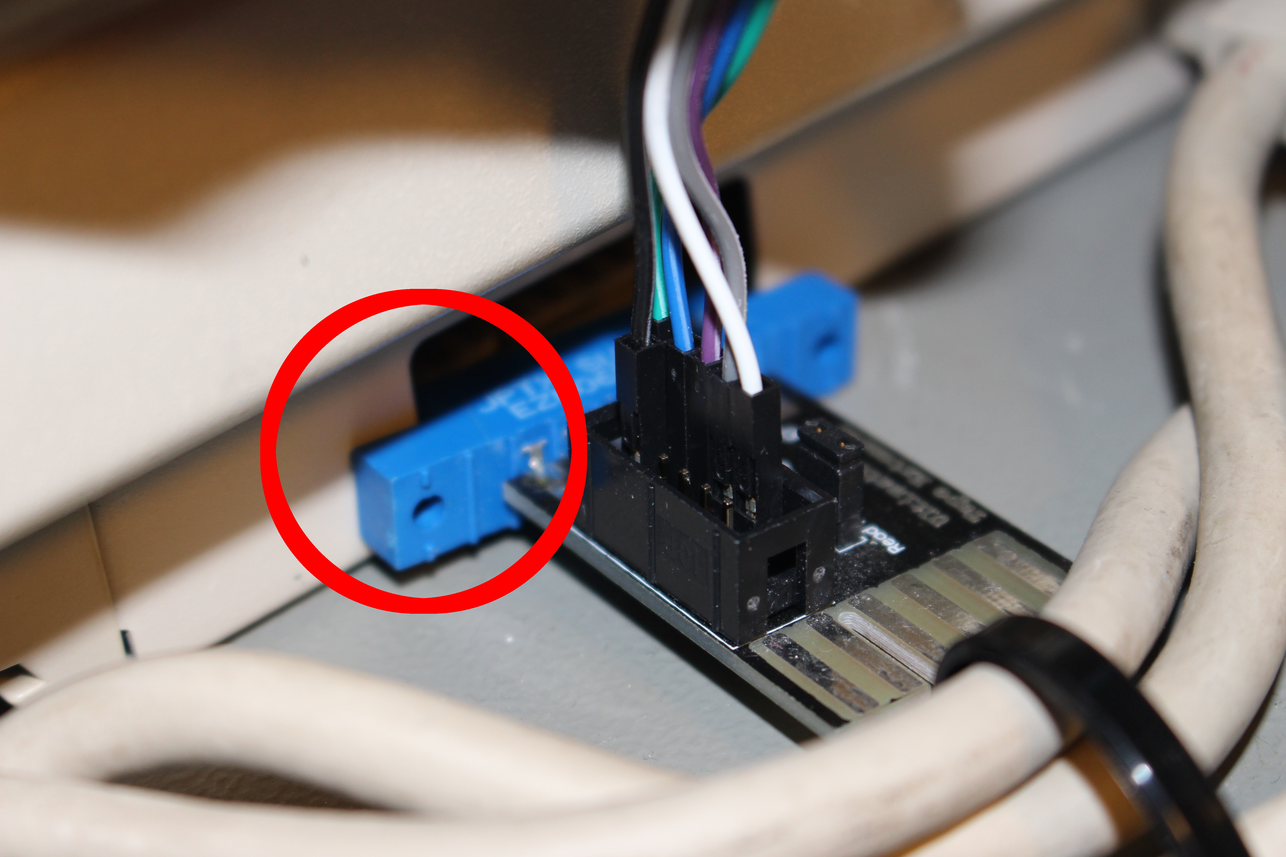 The tape header on the extender is too wide to be plugged into the C128D. I was lazy and only connected 6 wires here, but recommended is connecting all 10 to prevent noise/stray signals (Thanks e5frog).
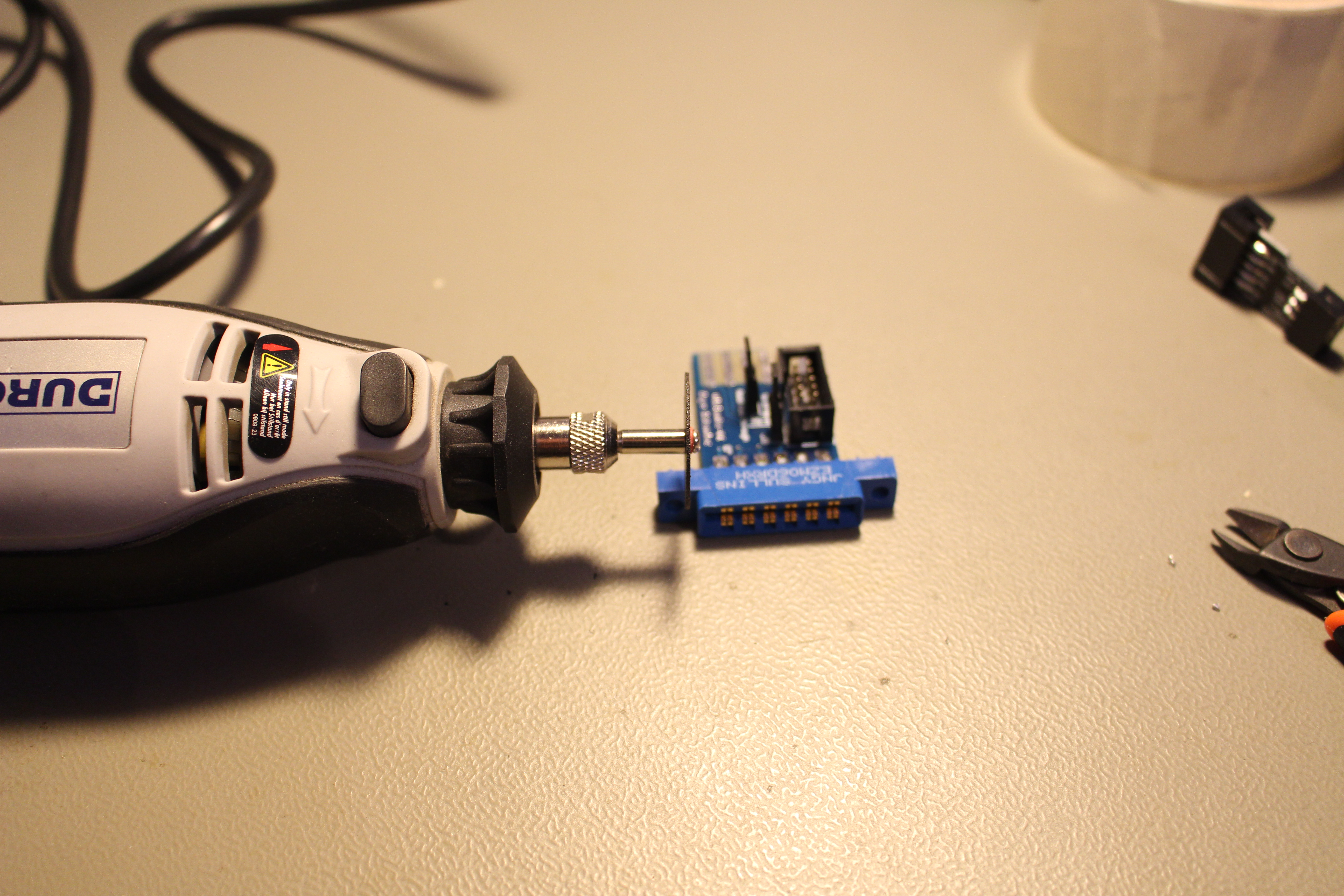 This is something a Dremmel can take care of, just cut off the additional plastic used for screws.
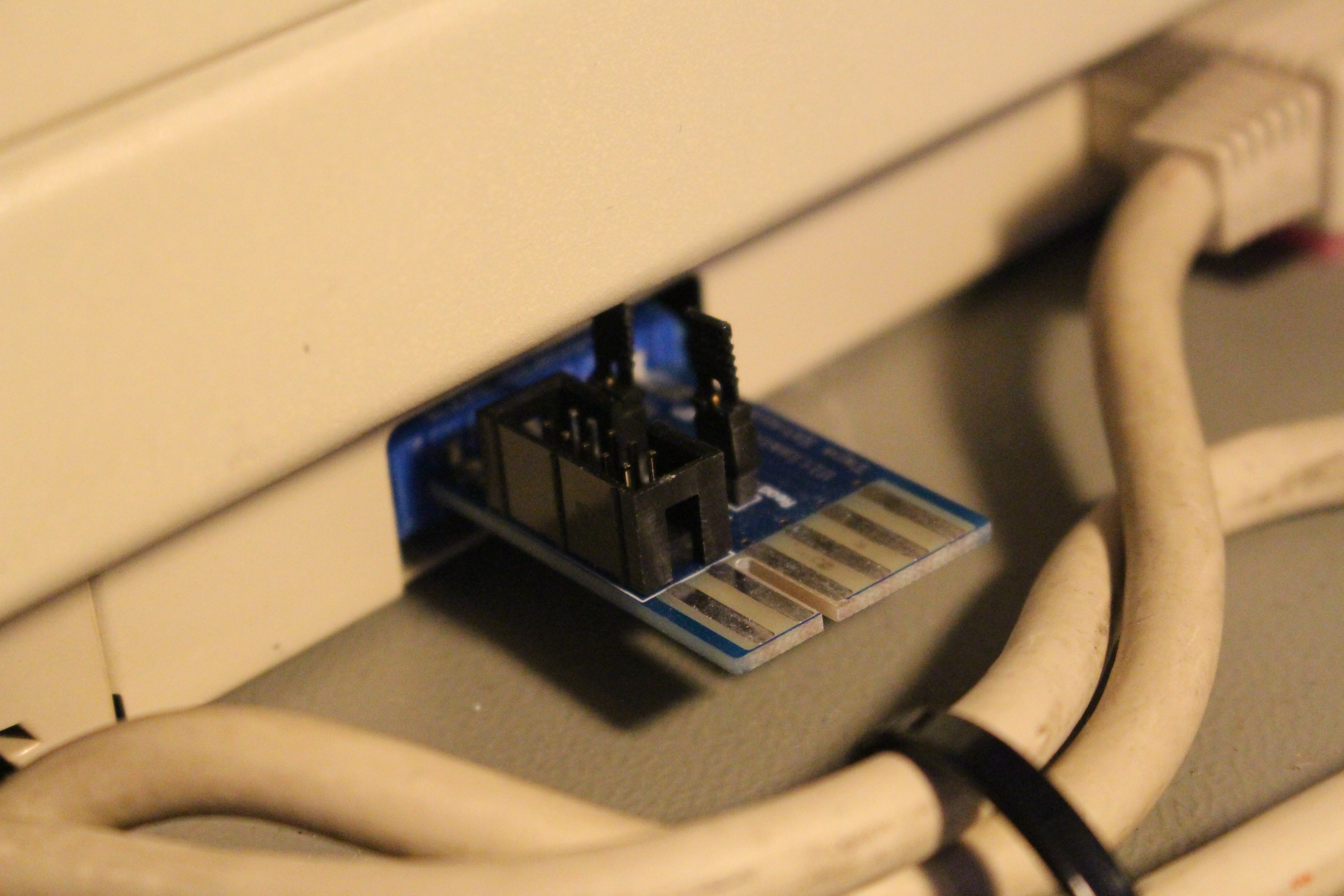 Violá, ready to use the 1541 Ultimate 2 tape extender.